酒店取电开关故障排查指南:诊断与修复客房读卡器故障
面向维护工程师的酒店取电开关故障排查指南,涵盖无供电、指示灯常亮、继电器失效、读卡错误等常见故障。
酒店取电开关故障排查指南是为服务读卡器、继电器和负载控制电路(为客房插座、照明和空调供电)的工程与维护团队提供的实用诊断参考。当客人插入卡片却无任何灯光亮起,或退房后电源始终未切断时,根因可能存在于墙盒、读卡器、继电器与连接负载之间的任意环节,因此结构化清单远比试错法更有效。本指南将梳理最常见的故障模式、可复现的分步测试流程、工具车必备工具,以及就地维修与整体更换的明确决策规则。带电作业存在真实风险,故本指南每一步均假设在接触任何接线端子前,电源已隔离并上锁。
酒店取电开关故障排查指南简介
酒店取电开关是安装在客房入口处的负载控制面板,仅在有效卡片插入期间为客房供电,卡片拔出后切断供电。它本质上是一个外壳内集成的三大子系统:验证凭证的读卡部分、解读卡片状态的逻辑或控制部分、以及将火线接通至负载的机电或固态开关部分。大多数民用级取电开关的输入电压为 100 至 240 VAC,切换负载 8 至 16 安培,继电器在卡片插入时保持闭合,卡片拔出后经 10 至 90 秒或更长延时断开。本指南采用现场工程师的思路处理故障:从可观测症状入手,缩小至子系统,在客房恢复服务前确认修复。因同一物理单元可表现出数十种不同行为,资料按症状优先、测试流程次之组织,以便维护团队直接跳转至匹配工单投诉的章节。
测试前的正常单元行为
在开始酒店取电开关故障排查指南前,回顾健康单元的预期行为有助于识别异常读数。将有效卡片正对插槽插入。读卡器应确认卡片,通常通过指示灯变色指示,继电器应在约 0.5 至 1 秒内动作,将火线切换至插座和灯具。拔出卡片后,继电器应在编程的延时断电区间内保持闭合,随后断开切断负载。客房整夜无人入住时,开关应维持低待机状态,仅从控制电源汲取几毫瓦功耗。任何偏离此序列的现象——无论是灯光从未亮起、继电器吸合却保持断开、或卡片拔出后负载持续运行——都是诊断线索的起点,本指南将助您循迹排查。
您实际在测试的四大子系统
整个酒店取电开关故障排查指南归结为四个组件。第一是电源输入级:保险丝、压敏电阻和稳压电源,将市电转换为逻辑电路所需的安全直流电轨。第二是读取级:磁条卡的光学传感器,或非接触式卡的 RFID 读头线圈与天线,仅在匹配凭证存在时产生信号。第三是控制级:通常为单片机或比较器,决定是否激励继电器及卡片离开后的保持时长。第四是输出级:实际承载负载电流的继电器触点或双向可控硅。实践中,约一半现场上报故障实为卡片、布线或负载问题,而非开关本身,因此本诊断法刻意先查外部,再定性设备。
酒店取电开关故障排查指南:识读常见症状
贯彻酒店取电开关故障排查指南最快的路径,是从客人或保洁员实际上报的症状入手,将其映射至最可能的故障子系统。大多数投诉归纳为七大模式,每一模式指向不同的排查重点。下表汇总症状、常见成因与首查位置,后续章节给出各行的详细测试步骤。
| 症状 | 最可能成因 | 首查位置 |
|---|---|---|
| 插卡无指示、无供电 | 无输入电压或控制电源损坏 | 测量输入端子市电电压 |
| 插卡指示亮、无输出 | 继电器未吸合或负载开路 | 核验继电器通断与负载回路 |
| 卡片无效、读取失败 | 卡片类型错误、读卡器脏污、信号弱 | 用已知良好有效卡测试 |
| 拔卡后电源不切断 | 触点粘连或卡滞 | 延时窗口后测量继电器输出 |
| 指示灯持续常亮 | 控制逻辑卡死或输出短路 | 拔卡观察延时周期 |
| 延时过短或过长 | DIP 开关设置错误或定时电容老化 | 核对延时配置并台架测试 |
| 完全无输出、单元死机 | 保险丝熔断、走线开路、电源模块故障 | 检查保险丝与输入供电电压 |
插卡无指示、无输出
这是最常见的报修,通常指向电源输入级而非读取级。若插入已知良好卡片时指示灯完全不亮,说明控制板无供电轨,原因可能是:给开关供电的房间断路器跳闸、输入接线松动或反接、内部保险丝开路、或板载稳压器失效。用万用表在火线与零线输入端子快速测量电压,一分钟内即可排查大部分情况。若市电存在但板卡仍无反应,问题已锁定在内部电源模块,属于维修或更换决策,而非接线修复。务必在打开墙盒前确认给开关供电的断路器确实有电输出。
插卡指示亮、继电器无输出
若指示灯正常但负载始终不通电,读取与控制级大概率正常,故障落在输出级或负载端。继电器可能未得电吸合、触点烧蚀导致高阻、或从继电器输出至插座灯具的接线断裂。可在插卡状态下测量继电器输出端子通断来区分:若输出端子导通但客房仍暗,故障在下游负载接线;若输出端子持续断开,故障在继电器或驱动其的控制器内部。
读卡失败或忽略卡片
当开关对插入卡片无反应,常见原因包括:卡片类型不匹配、读卡槽磨损或脏污、RFID 信号微弱、或卡片编码不当。磁条卡需确认磁条朝向正确且读头清洁;RFID 卡需确认频率与编码与开关配套的锁系统一致(如 125 kHz EM 或 13.56 MHz Mifare)。确凿测试是插入万能卡或相邻房间的已知良好卡;若其正常,说明开关无故障,问题在客人卡片。
拔卡后电源持续不切断
拔卡后仍持续供电,指向触点粘连、开关器件击穿、或控制逻辑卡在激励态。此症状亦造成能源浪费与安全隐患,因空房灯光空调持续运行。延时窗口结束后,测量继电器输出端通断。若拔卡状态下仍导通,输出器件卡死,开关须整体更换,因粘连触点现场难以可靠修复。
指示灯持续常亮
指示灯状态从不改变,视为控制逻辑症状。卡片可能卡在插槽顶住读头、微动开关机械卡滞、或控制器未检测到卡片离开。核实插槽物理空闲、拔出卡片、给足延时窗口时间。若无论卡片位置指示灯常亮,则读卡器微动开关或逻辑板故障。
拔卡后延时过短或过长
异常延时断电间隔通常为配置问题而非硬故障。多数开关通过 DIP 开关或跳线块设定保持时间(约 15 秒至数分钟),设置错误会导致延时不符合酒店标准。若配置未变但延时不稳定或漂移,逻辑板上定时电容可能老化。先按说明书核对 DIP 开关位置,再台架测试重复性,排除元件故障前勿盲目判定。
酒店取电开关故障排查指南:分步诊断流程
任何酒店取电开关故障排查指南的核心,是一套可复现的序列,在不一次性拆卸所有组件的前提下隔离故障。下述方法备齐工具时单间约需 10 至 15 分钟,对磁条、RFID 及混合型开关通用,因其按电源→读取→开关→时序的顺序测试。每步设计均使正/负结果直接指向责任子系统及后续动作。接触任何端子前,务必在配电箱隔离分支回路并上锁挂牌,因墙盒裸露市电即使房间看似漆黑仍具触电危险。
步骤 1:确认供电与输入完好
从输入端开始。隔离电路后打开墙盒,辨识火线、零线及地线(如有),目检端子是否松动、腐蚀或烧焦。复原接线、恢复供电,测量开关接入状态下的输入端电压。读数在 100 至 240 VAC 之间,确认供电与接线正常,可进入读取与控制级排查;无读数则问题在上游断路器或馈线,非开关本身。
步骤 2:核验读卡级
确认输入供电后,插入同类型的已知良好、正确编码卡片。观察指示灯、聆听继电器吸合声。若指示灯变化但继电器无声,控制级未驱动输出,指向逻辑板;若指示灯与继电器均无反应,读取级未检测到凭证。在第二台已知良好开关上测试同一张卡,排除客人卡片损坏后再定性设备。
步骤 3:测试继电器与负载回路
持握有效卡,用通断档确认继电器输出端子闭合;再测量负载端(插座或灯具)是否真有电压。三种结果即定乾坤:输出导通且负载带电——开关良好,原投诉为瞬态故障;输出导通但负载无电——故障在房间接线或灯具;输出断开——继电器或控制器内部故障。
步骤 4:核查延时与保持时序
拔出卡片,计时继电器保持闭合时长。实测保持时间与 DIP 开关或跳线设定对比。巨大偏差指向配置错误,按酒店标准重设即可;设定正确但保持时间随机或漂移,指向定时元件老化,属质量问题,倾向更换。至少连续运行三次拔卡循环,确认时序稳定后再签署结案。
步骤 5:台架离线测试
若墙上测试仍存疑,拆下开关至台架,接保险熔断器保护的测试电源、测试卡、及小功率测试灯或 100 瓦等效电阻负载。台架测试排除房间接线变量,五分钟内给出读取、继电器、延时的干净结论。在设备标记测试结果,便团队知晓是否可回库存或须报废。
支撑酒店取电开关故障排查指南的测试工具
精简工具清单让整个酒店取电开关故障排查指南更快更安全,因极少故障能靠肉眼可靠判断。下列工具覆盖输入电压、继电器通断、带电负载、卡片有效性,均可装入标准工程师包。
| 工具 | 验证内容 | 健康单元典型读数 |
|---|---|---|
| 数字万用表 | 输入电压、继电器通断、漏电流 | 100-240 VAC 输入;吸合时近零欧姆 |
| 非接触验电器 | 非接触检测带电体 | 靠近带电导体时亮灯 |
| 通断探针/音频测线仪 | 继电器触点闭合 | 继电器吸合时鸣响/稳定 |
| 测试卡(已编码) | 读卡与编码匹配 | 指示灯变化且继电器吸合 |
| 测试灯/模拟负载 | 真实负载表现 | 插卡灯亮,延时后灭 |
| 备用开关/转接板 | 隔离开关与接线 | 台架上验证故障单元 |
万用表在各步骤中的用法
数字万用表贯穿整个酒店取电开关故障排查指南。用交流电压档确认输入供电,用通断与低欧姆档检查继电器触点闭合,用直流电压档核验板载排针处的控制电轨(如有)。探针保持绝缘测试头,接线前先选正确量程,因在电阻档读带电电压等效短路,会跳闸。带背光显示与蜂鸣通断的表笔,在暗墙腔内是真正的提效神器。
测试卡比看上去更关键
令人惊讶的一级修复失败,往往因测试凭证错误。为使酒店取电开关故障排查指南可靠,您至少需要一张正确卡类型、正确编码、专供诊断且从不发给客人的已知良好卡。若该卡失效,您发现的是开关读取级或编码器问题,而非客人体验。每辆维护车备两张测试卡,防单张磨损导致假阳性。
属于工具包的安全装备
电气诊断的安全性取决于诊断前的隔离。除仪表与卡片,工具包应含:分支配电箱上锁挂牌套装、绝缘螺丝刀、开关设备用绝缘手套、近电报警器作冗余验证。铁律:用额定万用表与非接触验电器双重确认无电后再开箱,并上锁断路器防他人误合闸。本指南无任何排查步骤值得以触电为代价。
酒店取电开关故障排查指南:各故障深度诊断
前文流程给出序列,本节逐症状深入酒店取电开关故障排查指南,解释可能的物理机制与确认各故障的确切读数。每个症状以简短自包含答复开头,再拆解为成因、测试、修复三段,工程师可直达匹配工单的行。并列阅读还能揭示子系统如何倾向某诊断而非另一诊断,因相同指示状态常由两种截然不同的根因导致,需相反的修复动作。
为何电源模块故障导致开关完全死机
完全死机——无指示、无继电器、无负载——几乎总是电源输入问题,而非读取问题,因无直流供电轨,所有后级均饥饿。按概率顺序:分支断路器跳闸或损坏、端子处火零线松动或反接、内部保险丝开路、控制板稳压器失效。确认测试:万用表测输入端子;若读到预期 100-240 VAC 但板卡仍暗,故障已入内部,更换决策已定;若输入端无读数,先在配电箱核实断路器与馈线再动手。复原、送电、复测,合箱。
为何弱磁条导致间歇性故障
间歇性故障——时好时坏——是脏污或磨损磁条与读头不稳定读取的经典特征。磁条随摩擦、磁场暴露、反复插拨退化,高频使用的客人卡虽仍有编码却读取不良。指南中正确测试:同一开关上对比可疑卡与同类型已知良好卡。良好卡稳定、可疑卡不稳,确认为卡片侧故障,对策是重新发卡而非换开关。擦净插槽与磁条,复测再填报告。
为何 RFID 开关忽略非接触式卡片
RFID 取电开关忽略全新 125 kHz 或 13.56 MHz 卡,最常因卡片协议与读卡器不匹配,而非读卡器损坏。不同锁系统在不同频率与数据格式编码,A 系统卡片虽外观相同,也无法触发配对 B 系统的开关。确认测试:将卡贴近开关观察是否有任何应答,再试该房间自带系统的已知卡。正确卡有效则开关健康,客人卡仅属错投人群;正确类型卡均无效,则读头线圈或板载驱动失效,须整体更换。
为何粘连触点导致持续供电
拔卡后仍供电,指向触点在负载下粘连或双向可控硅击穿。触点粘连时,机械连杆虽控制线圈失电仍无法断开导通,负载无限期持续供电。指南中确认测试极简:拔卡、等满延时窗口、测输出端通断。拔卡状态下仍导通,输出器件卡死,故障永久,必须更换。切勿尝试敲击或反复通电“敲回”继电器,因瞬间断开的粘连触点仍受损,可能再次在负载回路失效。
为何 DIP 开关设置改变实测延时
延时断电不符酒店标准,通常为配置问题。多数开关通过 DIP 开关或跳线选定保持时间(约 15 秒至数分钟),拨错位置产生的延时在保洁员眼中像故障。确认核查:对照机身印刷索引与说明书核对 DIP 位置,拨至酒店标准,跑拔卡循环。若延时随即符合标准且三次重复稳定,单元健康,配置即修复。仅当配置未变而延时随机漂移时,才怀疑定时电容老化并转向更换。
为何接触不良或端子松动伪装成继电器故障
有时读数指向继电器故障,实为下游负载接线松动或腐蚀。继电器吸合、输出端子通断良好,但客房不亮,断点在开关至灯具的接线而非开关内部。确认步骤:万用表从继电器输出端沿线追踪至首个插座灯具,找火线信号消失点。拧紧松动端子、修复断导体、复测。此区分意义大:避免因接线故障误报废良好开关,也提醒将接线而非仅设备视为受测电路一部分。
常见问题:酒店取电开关故障排查指南 FAQ
| 问题 | 简短回答 |
|---|---|
| 为何在别的房间能用的卡这儿不行? | 不同开关或锁系统编码不同;请用该房间系统的卡 |
| 粘连的继电器能修吗? | 不能,整体更换,现场无法安全修复 |
| 保险丝烧了一定是开关坏了? | 不一定;先查断路器及外部保险丝面板 |
| 延时断电应设多久? | 拨 DIP 开关至酒店标准,通常 15 秒至数分钟 |
| 读卡器脏了须换整机? | 否,先清洁插槽与磁条,复测再决定 |
酒店取电开关故障排查指南:维修与更换决策
指南的重要一环,是判断何时可就地恢复、何时须拆下更换。一般而言,端子松动、配电箱外部保险丝熔断、延时开关设置错误、读卡槽脏污,属零部件成本为零的就地可修项。内部故障如稳压器损坏、定时电容失效、走线开裂、触点粘连,几乎总是更换比维修划算,因人工成本常超新开关价格,且修复件通常无质保。下表给出实用决策矩阵。
| 状况 | 就地维修 | 更换 | 备注 |
|---|---|---|---|
| 火/零线输入端子松动 | 是 | 否 | 重新扭矩并复测 |
| 外部保险丝熔断 | 是 | 否 | 查明并修复成因 |
| 磁条读头脏污 | 是 | 否 | 清洁后复测 |
| 延时 DIP 设置错误 | 是 | 否 | 设为酒店标准 |
| 内部保险丝开路 | 否 | 是 | 可能有内部故障 |
| 继电器触点粘连 | 否 | 是 | 无法安全修复 |
| 稳压器失效 | 否 | 无现场备件 | |
| PCB 开裂或烧焦 | 否 | 是 | 涉及安全 |
| 进水或腐蚀损坏 | 否 | 是 | 整体更换 |
何时就地维修合理
特定故障属调整或清洁范畴而非元件损坏,可就地维修。安全重新扭矩的松动端子、拨至酒店标准的延时开关、清洁灰尘的读头,均能在分钟级恢复服务且零成本。关键原则:维修仅在单元通过与新品相同的验证时有效——即干净读卡、可靠吸合、正确延时,至少三循环验证通过后方可释放房间。
何时更换为正确决策
凡怀疑密封单元内部存在电气或机械损伤,更换为正确决策。触点粘连、供电级烧毁、走线开裂、进水损坏,修复均将安全隐患留存且无担保。商业运营中停机成本亦关键:一次更换比两次可能不持久的维修尝试更廉价。多数酒店设定简明规则:仅尝试非电气、非损坏类就地修复,内部故障一律更换。
同规格替换原则
更换时,安装电压、额定电流、卡片类型、延时行为、安装尺寸均与拆下单元一致的机型,保持房间接线与酒店卡片标准兼容。上墙前用测试卡确认新机读取正常,维护日志记录日期与房号。现场备少量同型号备件,可缩短未来更换周期,避免因等备件导致客房长时间停用。
预防故障:超越单次酒店取电开关故障排查指南
最好的酒店取电开关故障排查指南以预防收尾,因多数常见故障可通过规范安装、洁净环境、计划验证来规避。配以合适断路器、适配额定保险丝、稳定电压、洁净干燥环境的开关,服务调用本就稀少。在预防性维护日历加入少量例行检查,即可大幅降低团队被动排查的次数。
预防故障的安装习惯
规范安装能在故障萌芽前消除大部分隐患。按说明书规定导线规格与扭矩施工,合箱前保持盒体干燥,走线避开可能磨损绝缘的金属锐边。确认供电电压匹配开关额定、断路器按负载电流选型。轻柔安装、端子洁净、PCB 无应力的单元,寿命期内极少出现松动接头或走线开裂。
清洁与卡片管理纪律
读卡槽与卡面是系统最高频受损部位。定期以柔软干布清洁读头与卡面,避免卡片接触磁铁与热源,在磨损卡失读前主动换发。因读取级是前沿防线,保持插槽无尘、编码有效,是酒店可获得的最简便可靠性红利。
计划验证与备件储备
将低成本验证巡检纳入预防性维护:轮换计划中每间房插入测试卡,观察指示灯、继电器、延时一次,记录异常单元。现场储备少量标准机型备件,确诊故障当日即可换装。落实这些习惯,团队执行酒店取电开关故障排查指南的时间将大幅下降,客人舒适度得到持续保障。
酒店取电开关故障排查指南结语
遵循结构化的酒店取电开关故障排查指南,让维护团队从客人投诉到客房恢复,拥有一条快速、安全的路径。方法始于症状,按电源→读取→开关→时序推进,用万用表与已知良好卡将开关与接线、负载剥离,在就地调整与整体更换间做出清晰决策。全流程设计为可教学:保洁主管可记录精确症状,工程师无需从头重新诊断即可行动;同一清单交给新技术员亦可信赖执行。
保障指南安全可靠的三条铁律
三个习惯让整个酒店取电开关故障排查指南在日常中经得起考验。第一,接触端子前隔离上锁电源,用额定万用表与非接触验电器双重确认无电,因墙盒裸露市电无论房间看似多暗皆具触电危险。第二,始终用正确类型的已知良好卡测试,而非客人卡,因磨损或错类凭证产生假故障,浪费服务趟次。第三,对存疑单元离墙台架测试,接保险测试电源与测试灯,让最终定论基于读取、继电器、延时的干净读数,而非暗腔中的猜测。
健康开关期望您接下来做什么
通过指南的单元无需短期再动手。确认读取级洁净、延时符合酒店标准、负载接线正确、保险丝与断路器按电流选型,开关将可靠服务至下一次计划巡检。对少数内部故障单元,立即执行更换规则而非修补,因粘连触点、损坏板卡、进水损坏均为永久性,更换才有担保。落实这些习惯,多数客房单趟恢复,排查积压锐减,每一次插卡,开关都仅做它该做的事——可靠控制负载。多数服务调用经流程梳理后成因简单,极少真正内部故障被快速捕获,避免疲劳单元带病服役。接触端子前隔离上锁电源,存疑单元台架测试,内部电气损坏一律更换。保持读卡槽洁净、配用适配保险丝与断路器、储备同型号备件,开关将提供多年可靠的负载控制。
本文部分内容由 AI 生成,并经优化以确保专业准确性与可读性。
A hotel key card switch troubleshooting guide is a practical diagnostic reference for engineering and maintenance teams that service the card readers, relays, and load-control circuits that power guest room outlets, lighting, and air conditioning. When a guest inserts their card and nothing lights up, or the power never cuts off after checkout, the root cause can sit anywhere between the wall box, the card reader, the relay, and the connected load, so a structured checklist is far more effective than trial and error. This guide walks through the most common failure modes, a repeatable step-by-step test flow, the tools you need on the trolley, and clear decision rules for when a unit can be repaired in place versus when it should be swapped for a new switch. Electrical work on live circuits carries real risk, so every step here assumes that power is isolated and locked out before any terminal is touched.
Introduction to the Hotel Key Card Switch Troubleshooting Guide
A hotel key card switch is a load-control panel mounted at the room entrance that energizes guest room power only while a valid card is inserted and cancels it when the card is withdrawn. It is essentially three subsystems in one enclosure: a card-reading section that validates the credential, a logic or controller section that interprets the card state, and an electromechanical or solid-state switching section that connects the line to the load. Most residential-style card switches operate at 100 to 240 VAC input and switch a load of 8 to 16 amps, with a relay that remains closed while the card is present and opens after a delay of 10 to 90 seconds or more when the card is removed. This guide approaches failures the way a field engineer would, starting from observable symptoms, narrowing to a subsystem, and confirming the fix before the room is returned to service. Because the same physical unit can exhibit dozens of different behaviors, the material is organized by symptom first and by test procedure second, so that a maintenance team can jump straight to the section that matches the complaint on the work order.
How a Working Unit Behaves Before You Test Anything
Before you start the hotel key card switch troubleshooting guide, it helps to recall the expected behavior of a healthy unit so abnormal readings stand out. Insert a valid card front and center into the slot. The reader should confirm the card, usually with an indicator LED that changes color, and the relay should energize within about 0.5 to 1 second, switching line power to the outlets and fixtures. Remove the card and the relay should remain closed through the programmed delay-off interval, then open to drop the load. With the room unoccupied overnight, the switch should hold a low stand-by state that draws only a few milliwatts from the control supply. Any deviation from this sequence, whether it is a light that never turns on, a relay that clicks but stays open, or a load that keeps running after the card is gone, is the start of a diagnostic trail that the rest of this guide will help you trace.
The Four Subsystems You Are Really Testing
The entire hotel key card switch troubleshooting guide reduces to four components. First is the power input stage, the fuse, MOV, and voltage-regulating supply that turns line voltage into a safe DC rail for the logic. Second is the reading stage, an optical sensor for magnetic stripe cards or an RFID reader coil and antenna for contactless cards, which produces a signal only when a matching credential is present. Third is the control stage, usually a microcontroller or comparator that decides whether to energize the relay and how long to hold it after the card leaves. Fourth is the output stage, the relay contacts or TRIAC that actually carries load current. In practice, roughly half of all field-reported failures turn out to be the card, the wiring, or the load rather than the switch itself, which is why the diagnostic method here deliberately checks externals before it blames the unit.
Hotel Key Card Switch Troubleshooting Guide: Reading the Common Symptoms
The fastest way to work through any hotel key card switch troubleshooting guide is to start from the symptom a guest or housekeeper actually reports and map it to the most likely failing subsystem. Most complaints fall into seven patterns, and each one points at a different place to investigate. The table below summarizes the symptom, the usual cause, and the first place to look, and the sections that follow it give the detailed test for each row.
| Symptom | Most Likely Cause | First Check |
|---|---|---|
| Insert card, no indicator, no power | No input power or dead control supply | Measure line voltage at the input terminals |
| Insert card, indicator on, no output | Relay not energizing or load open | Verify relay continuity and the load circuit |
| Card has no effect, reading fails | Wrong card type, dirty reader, weak signal | Test with a known-good valid card |
| Power never cuts off after card removal | Welded or jammed relay contacts | Measure relay output after the delay window |
| Indicator light stays on constantly | Stuck control logic or shorted output | Remove card and watch the delay cycle |
| Delay is too short or too long | Mis-set DIP switch or dying timing capacitor | Check the delay configuration and bench test |
| No output at all, unit totally dead | Blown fuse, open trace, failed supply | Inspect fuse and input supply voltage |
Insert Card, No Indicator, No Output
This is the most common call, and it usually points at the power input stage rather than the reading stage. If the indicator LED does not come on at all when a known-good card is inserted, the control board has no supply rail, which means either the room breaker feeding the switch is tripped, the input wiring is loose or reversed, the internal fuse is open, or the on-board voltage regulator has failed. A quick voltage check with a multimeter at the line and neutral input terminals answers most of these in under a minute. If line voltage is present but the board still appears dead, you have isolated the problem to the internal power supply, which is a repair or replace decision rather than a wiring fix. Always confirm that the breaker that feeds the switch is actually supplying power before you open the wall box.
Insert Card, Indicator On, No Relay Output
If the indicator lights correctly but the load never comes on, the reading and control stages are probably healthy and the fault sits in the output stage or the load. The relay may be failing to energize, the relay contacts may be pitted and high in resistance, or the wiring from the relay output to the sockets and fixtures may be broken. You can separate these by measuring continuity across the relay output terminals while a card is inserted. If the output terminals become continuous but the room stays dark, the problem is downstream in the load wiring. If the output terminals stay open, the problem is the relay or the controller driving it.
Card Reading Fails or Ignores the Card
When the switch simply ignores an inserted card, the likely causes are a card of the wrong card type, a worn or dirty reader slot, a weak RFID signal, or a card that has not been properly encoded. For magnetic stripe cards, check that the stripe faces the correct direction and that the reader head is clean. For RFID cards, confirm the card uses the same frequency and encoding as the lock system the switch is paired with, such as 125 kHz EM or 13.56 MHz Mifare. A sure test is to insert the master or a known-good card from a neighboring room; if that works, the switch is fine and the guest card is the issue.
Power Never Cuts Off After Card Removal
A switch that keeps the power on after the card is removed points to a relay whose contacts are welded shut, a shorted switching device, or control logic stuck in the energized state. This symptom also creates an energy-waste and safety issue, because lights and air conditioning keep running with the room empty. After the delay window passes, measure continuity across the relay output. If it stays continuous with the card removed, the output device is stuck and the switch should be replaced, because a welded relay is not reliably repairable in the field.
Indicator Light Stays On Constantly
When the indicator never changes state, treat it as a control-logic symptom. The card may be stuck in the slot against the reader, the micro-switch may be mechanically bound, or the controller may be failing to detect the card leaving. Verify that the slot is physically free, remove the card, and give the delay window time to expire. If the light stays on regardless of card position, the reader micro-switch or the logic board is at fault.
Delay Too Short or Too Long After Card Removal
An abnormal delay-off interval is usually a configuration issue rather than a hard failure. Many switches expose a DIP switch or jumper block that sets the hold time from about 15 seconds to several minutes, and a mis-set switch produces a delay that does not match the property standard. If the delay is inconsistent or drifts over time with no config change, the timing capacitor on the logic board may be aging. Confirm the DIP switch position against the manual first, then bench-test repeatability before assuming component failure.
Hotel Key Card Switch Troubleshooting Guide: The Step-by-Step Diagnostic Flow
The core of any hotel key card switch troubleshooting guide is a repeatable sequence that isolates the fault without removing every component at once. The method below takes roughly ten to fifteen minutes per room when the tools are on hand, and it works the same way for magnetic, RFID, and hybrid switches because it tests power first, reading second, switching third, and timing last. Each step is designed so that a positive or negative result tells you exactly which subsystem to blame and what to do next. Always isolate the branch circuit at the panel and apply lockout/tagout before any terminal is touched, because exposed line voltage at the wall box is a shock hazard even when the room appears dark.
Step 1: Confirm Power and Input Integrity
Start at the input. With the circuit isolated, open the wall box, identify the line, neutral, and any earth conductor, and visually inspect the terminals for looseness, corrosion, or scorching. Reconnect, restore power, and measure 100 to 240 VAC across the input with the switch in circuit. A healthy reading here confirms the supply and wiring, so you can move to the reading and control stages. A missing reading means the problem is upstream in the breaker or feed, not in the switch.
Step 2: Verify the Card-Reading Stage
With input power confirmed, insert a known-good, correctly encoded card of the same type the room is supposed to accept. Watch the indicator and listen for the relay click. If the indicator changes but the relay does not click, the control stage is not pulsing the output, which points to the logic board. If neither the indicator nor the relay responds, the reading stage is not detecting the credential. Test the same card in a second, known-good switch to rule out a bad guest card before you condemn the unit.
Step 3: Test the Relay and Load Circuit
Hold a valid card in place and use continuity mode to confirm that the relay output terminals become closed. Then verify that voltage actually reaches the outlets or fixtures by measuring at the load. Three outcomes resolve the picture: output closed and load live means the switch is good and the original complaint was transient; output closed but load dead means the fault is in the room wiring or the fixture; output open means the relay or controller is at fault inside the switch.
Step 4: Check the Delay and Hold-On Timing
Remove the card and time how long the relay stays closed. Compare the measured hold time with the DIP switch or jumper setting. A gross mismatch points to misconfiguration, which you can correct by setting the switch to the property standard. A correct setting but clearly random or drifting hold time points to a failing timing component, which is a quality issue that favors replacement. Run the removal cycle at least three times to confirm the timing is consistent before you sign off.
Step 5: Bench-Test the Unit Off the Wall
If the in-wall tests leave doubt about whether the switch itself is good, remove it, take it to the bench, and test it with a card and a small test lamp or a 100-watt equivalent resistive load on a fused supply. A bench test removes the room wiring as a variable and gives a clean answer on read, relay, and delay in under five minutes. Mark the unit with the result so the team knows whether it is fit to return to stock or should be discarded.
Testing Tools That Support the Hotel Key Card Switch Troubleshooting Guide
A short tool list makes the entire hotel key card switch troubleshooting guide faster and safer, because very little can be diagnosed reliably by eye alone. The items below cover input power, relay continuity, live load, and card validity, and all of them fit in a standard engineer bag.
| Tool | What It Confirms | Typical Reading on a Healthy Unit |
|---|---|---|
| Digital multimeter | Input voltage, relay continuity, leakage | 100-240 VAC input; near-zero ohms when energized |
| Non-contact voltage tester | Presence of live voltage without contact | Lights when near an energized conductor |
| Continuity probe or tone | Relay contact closure | Tone/stability when relay is energized |
| Test card, encoded | Card reading and encoding match | Indicator changes and relay clicks |
| Test lamp or dummy load | Real load behavior | Lamp lights with card in, goes dark after delay |
| Spare switch or adapter | Isolation of switch versus wiring | Verifies the offending unit on the bench |
How the Multimeter Is Used in Each Step
The digital multimeter is the workhorse across the whole hotel key card switch troubleshooting guide. Use the AC voltage range to confirm the input supply, the continuity and low-ohms range to check relay contact closure, and the DC range to verify the control rail when available on the board header. Keep the probes on insulated inspection tips and set the meter to the correct range before connecting, because reading live voltage on a resistance range draws a short and can trip the supply. A meter with a backlit display and audible continuity is a genuine timesaver inside a dark wall cavity.
Why a Test Card Matters More Than It Seems
A surprising number of first-level fix attempts fail because the test credential is wrong. For the hotel key card switch troubleshooting guide to be reliable, you need at least one known-good card of the correct card type, correctly encoded, that you reserve for diagnostics and never hand to a guest. If that card stops working, you learn about the switch reading stage or the encoder, not the guest experience. Keep two test cards per maintenance trolley so a worn card does not produce a false pass.
Safety Tooling That Belongs in the Kit
Electrical diagnosis is only as safe as the isolation you perform before it. In addition to meters and cards, the kit should carry a lockout/tagout set for the branch panel, insulated screwdrivers, voltage-rated gloves for switchgear, and a proximity voltage tester as a redundant check. The rule is simple: verify dead with a rated meter and a non-contact tester before you open any box, and lock the breaker so someone else cannot restore power while your hands are inside. No troubleshooting step in this guide is worth a shock.
Detailed Diagnosis for Each Failure in the Hotel Key Card Switch Troubleshooting Guide
Where the earlier flow gives the sequence, this section goes symptom by symptom through the hotel key card switch troubleshooting guide and explains the likely physics and the exact readout that confirms each fault. Every symptom here begins with a short self-contained answer block, then breaks into the cause, the test, and the fix as separate pieces so an engineer can scan straight to the row that matches the work order. Reading these side by side also reveals how the subsystems recommend one diagnosis over another, because the same indicator states can often be produced by two different root causes that need opposite fixes.
Why a Failed Power Supply Produces a Completely Dead Switch
A completely dead switch, no indicator, no relay, no load, is almost always a power-input problem rather than a reading problem, because every other stage is starved without a DC supply rail. The probable causes in order are a tripped or failed branch breaker, a loose or reversed line and neutral pair at the terminals, an open internal fuse, or a failed voltage regulator on the control board. The confirming test is a multimeter across the input terminals; if you read the expected 100 to 240 VAC at the input but the board stays dark, the fault has moved inside the unit and the replace decision has already been made. If you read nothing at the input, open the panel and verify the breaker and the feeding conductor before you do anything else. Reconnect, restore and re-verify before closing the box.
Why a Weak Magnetic Stripe Produces an Intermittent Failure
An intermittent failure, one where the switch works on some inserts and not others, is the classic signature of a dirty or worn magnetic stripe and a reader head that reads it inconsistently. The magnetic stripe degrades with abrasion, exposure to magnets, and contact with the reader slot, so a guest card that sees heavy use reads poorly even though it is still encoded. In the hotel key card switch troubleshooting guide the correct test is to compare the suspect card against a known-good card of the same type in the same switch. If the good card reads reliably and the suspect card does not, you have confirmed a card-side fault and the answer is to encode a fresh card, not to replace the switch. Wipe the slot and the stripe clean, and re-test before you file the report.
Why an RFID Switch Ignores a Contactless Card
When an RFID hotel key card switch ignores a brand-new 125 kHz or 13.56 MHz card, the cause is most often a card that does not match the reader protocol, not a broken reader. Different lock systems encode cards on different frequencies and data formats, and a card from one system will not trigger a switch paired with another system even though both look identical. The confirming test is to pass the card under the switch and watch for any acknowledgment, then try a card known to come from the room's own system. If the correct card works, the switch is healthy and the guest card is simply from the wrong population. If no card of the correct type works, the reader coil or its driver on the board has failed and the unit should be replaced.
Why Welded Relay Contacts Hold Power On
A switch that keeps the room powered after the card is removed points to a relay whose contacts have welded shut under load or a TRIAC that has shorted. When the contact is welded, the mechanical link cannot break conduction even when the control coil is de-energized, so the load stays on indefinitely. The confirming test in the hotel key card switch troubleshooting guide is simple: remove the card, wait through the full delay window, and measure continuity across the relay output. If continuity persists with the card out, the output device is stuck, the fault is permanent, and the switch must be replaced. Do not attempt to exercise or tap the relay back into service, because a welded contact that momentarily opens is still damaged and can fail in the load path again.
Why a DIP Switch Setting Changes the Delay You Measure
A delay-off time that does not match the property standard is normally a configuration matter. Most card switches expose a DIP switch or jumper that selects the hold-on time from roughly 15 seconds up to a few minutes, and a switch set to the wrong position produces a delay that looks like a fault to a housekeeper. The confirming check is to compare the DIP switch position against the printed index on the unit and the manual, then set it to the property standard and run the removal cycle. If the delay then matches the standard and stays repeatable across three cycles, the unit is healthy and the configuration is the fix. Only when the delay drifts randomly with no config change should you suspect an aging timing capacitor and move to replacement.
Why Contact Corruption or Loose Terminals Mimic a Relay Failure
Sometimes the readout suggests a relay failure when the real problem is a loose or corroded load connection downstream. If the relay clicks and continuity is good at the output terminals but the room stays dark, the open is in the wiring between the switch and the fixtures, not in the switch. The confirming step is to chase voltage from the relay output to the first outlet and fixture with a multimeter, looking for the point where the live signal disappears. Re-tighten any loose terminal, repair any broken conductor, and re-test. This distinction matters because it saves a working switch from being discarded over a cabling fault, and it is a reminder to treat the wiring, not just the device, as part of the circuit under test.
FAQ: Common Questions in the Hotel Key Card Switch Troubleshooting Guide
| Question | Short Answer |
|---|---|
| Why does the switch ignore a card that works in another room? | Different switch or lock system encoding; use the room system card |
| Can I fix a relay that stays stuck on? | No, replace the unit, it is not safely field-repairable |
| Does a blown fuse always mean the switch is bad? | Not necessarily; check the breaker and any external fuse panel first |
| How long should the delay-off last? | Set the DIP switch to the property standard, usually 15 seconds to a few minutes |
| Do I need to replace the whole unit for a dirty reader? | No, clean the slot and stripe first, re-test, then decide |
Repair versus Replace in the Hotel Key Card Switch Troubleshooting Guide
Part of the hotel key card switch troubleshooting guide is knowing when a unit can be brought back to service and when it should be removed and replaced. In general, loose terminal screws, a blown external fuse at the panel, mis-set delay switches, and dirty card reader slots are repairable in place at no component cost. Internal failures such as a dead regulator, a failed timing capacitor, a cracked trace, or welded relay contacts are almost always more economical to replace than to repair, because labor alone can exceed the price of a new switch and a repaired unit typically carries no guarantee. The table below gives a practical decision matrix.
| Condition | Repair in Place | Replace | Notes |
|---|---|---|---|
| Loose L/N input terminal | Yes | No | Retorque and re-test |
| Blown external fuse | Yes | No | Identify and fix the cause |
| Dirty magnetic reader head | Yes | No | Clean, then re-test |
| Wrong delay DIP setting | Yes | No | Set to property standard |
| Open internal fuse | No | Yes | Internal fault likely |
| Welded relay contacts | No | Yes | Not safely repairable |
| Failed voltage regulator | No | Yes | No field replacement parts |
| Cracked or burned PCB | No | Yes | Safety-critical |
| Water or corrosion damage | No | Yes | Replace the unit |
When Repair in Place Is Justified
Certain faults are candidates for an in-place repair because they are adjustment or cleaning problems rather than component failures. A loose terminal safely re-torqued, a delay switch set to the property standard, and a reader head cleaned of dust all bring the room back to service in minutes with no cost beyond the engineer time. The critical rule is that a repair is only valid if the unit passes the same validation as a new one, meaning a clean card read, reliable relay closure, and correct delay, verified at least three cycles before the room is released.
When Replacement Is the Correct Call
Replacement is the right decision whenever the suspicion is electrical or mechanical damage inside the sealed unit. Welded relay contacts, a burned supply stage, cracked traces, and fluid damage are all cases where a repair would leave the safety risk in place and offer no guarantee. In a commercial operation the downtime math matters too: one visit to replace a switch is cheaper than two visits to attempt a repair that may not hold. Most properties set a simple rule, which is to attempt only non-electrical, non-damage repairs in place and to replace anything that fails internally.
The Replace-with-Same-Spec Rule
When a switch is replaced, install a unit with the same voltage, current rating, card type, delay behavior, and mounting dimensions as the one removed, so the rest of the room's wiring and the property's card standard remain compatible. Verify that the new unit accepts the same test card before you load it in, and record the replacement in your maintenance log with the date and room number. Keeping a small stock of the same model on property shortens any future swap and keeps guest rooms from staying down while a spare is sourced.
Preventing Failures: Beyond Each Hotel Key Card Switch Troubleshooting Guide
The best hotel key card switch troubleshooting guide ends with prevention, because most common failures are avoidable with disciplined installation, a clean working environment, and scheduled verification. A switch that is fed by a properly sized breaker, protected by an appropriately rated fuse, supplied with a stable voltage, and exposed to clean, dry conditions simply needs fewer service calls. Adding a handful of routine checks to the preventive maintenance calendar reduces the reactive number of troubleshooting visits a team has to run.
Installation Habits That Prevent Faults
Correct installation prevents a large share of faults before they appear. Use the conductor size and tightening torque the manual specifies, keep the box dry before you close it up, and run the in-wall wiring clear of any metal edges that could chafe insulation. Confirm the supply voltage matches the switch rating and that the breaker is sized for the load current. A gently installed unit with clean terminations and no strain on the PCB is far less likely to develop loose joints or a cracked trace over its life.
Cleaning and Card-Handling Discipline
The reader slot and the card surface are the most frequently abused parts of the system. Clean the reader and the card surface periodically with a soft, dry cloth, avoid exposing cards to magnets and heat, and replace worn guest cards before they stop reading. Because the reading stage is the front line, keeping the slot free of dust and the encoding current is one of the simplest reliability wins available to a property.
Scheduled Verification and Stocking
Add a low-effort verification pass to the preventive maintenance routine: insert a test card and watch the indicator, relay, and delay once per room on a rotating schedule, and log any unit that misbehaves. Keep a small stock of the standard switch model on property so a confirmed failure can be swapped the same day. With these habits in place, the time a team spends running the hotel key card switch troubleshooting guide drops sharply, and guest comfort stays protected.
Conclusion to the Hotel Key Card Switch Troubleshooting Guide
Following a structured hotel key card switch troubleshooting guide gives a maintenance team a fast, safe path from a guest complaint to a working room. The method always starts at the symptom, moves from power to reading to switching to timing, uses a multimeter and a known-good card to separate the switch from the wiring and the load, and makes a clear decision between an in-place adjustment and a swap. The whole routine is designed to be teachable, so a housekeeping supervisor can log a precise symptom and an engineer can act on it without re-diagnosing from scratch, and so the same checklist can be handed to a new technician with confidence.
The Three Rules That Keep the Guide Safe and Reliable
Three habits make the entire hotel key card switch troubleshooting guide dependable in daily use. First, isolate and lock out power before any terminal work, and verify it is dead with a rated meter and a non-contact tester, because exposed line voltage at the wall box is a shock hazard no matter how well the room appears. Second, always test with a known-good card of the correct type rather than the guest's card, because a worn or wrong credential produces a false failure that wastes a service visit. Third, bench-test any unit you are unsure about off the wall on a fused supply with a test lamp, so the final verdict rests on a clean reading of read, relay, and delay rather than a guess in a dark cavity.
What a Healthy Switch Should Ask You to Do Next
A unit that passes the guide does not need to be touched again quickly. Confirm the reading stage is clean, the delay matches the property standard, the load is correctly wired, and the fuse and breaker are sized for the current, and the switch will serve reliably until the next scheduled verification. For the minority of units that fail internally, apply the replace rule immediately rather than patching, because welded contacts, damaged boards, and fluid damage are permanent and a replacement holds the guarantee. With these habits in place, most rooms come back to service in a single visit, the troubleshooting backlog drops, and the guest experience is protected by a switch that simply does what it is supposed to do, every time a card goes in. Most service calls turn out to be a simple cause once the sequence is followed, and the few genuine internal failures are caught quickly so a tired unit is not left to fail in service. Isolate and lock out power before any terminal work, bench-test any doubtful unit, and replace anything with internal electrical damage. Keep the reading slot clean, use an appropriate fuse and breaker, and stock a spare of the same model, and the switch will give years of dependable load control.
Part of this article content is generated by AI and optimized for professional accuracy and readability.
不确定哪款传感器适合您的项目?
与我们的毫米波应用工程师免费咨询。
为您的酒店项目挑选合适的存在传感器
对比 3 种协议、查看酒店案例、下载安装指南
相关产品
2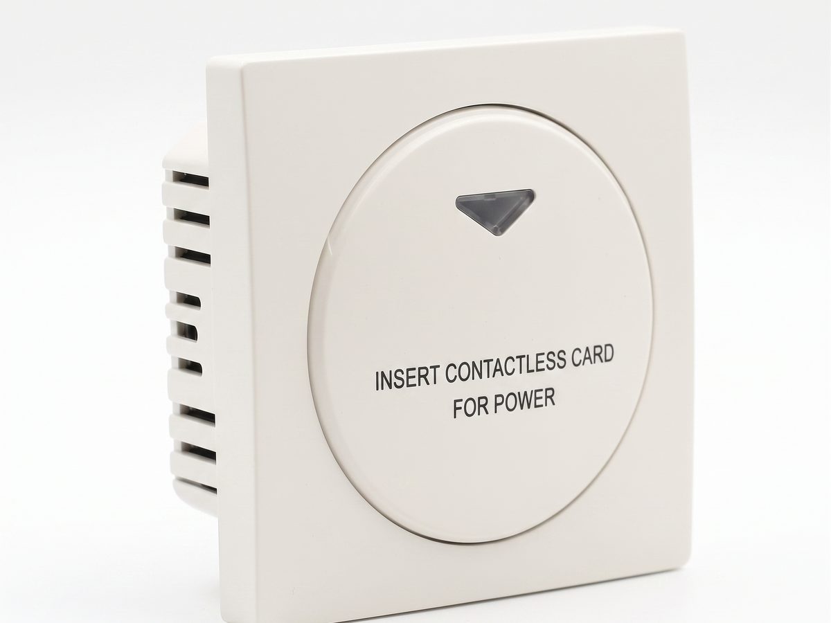
酒店取电开关 — 客房电源智能控制方案
酒店取电开关实现客房电源智能控制。RFID/IC卡识别,插卡取电,拔卡延时断电。220V交流,10A-16A,RS485或干接点。CE RoHS认证。OEM/ODM源头供应商。
当前页面已经把它作为下一步推荐内容直接指向。
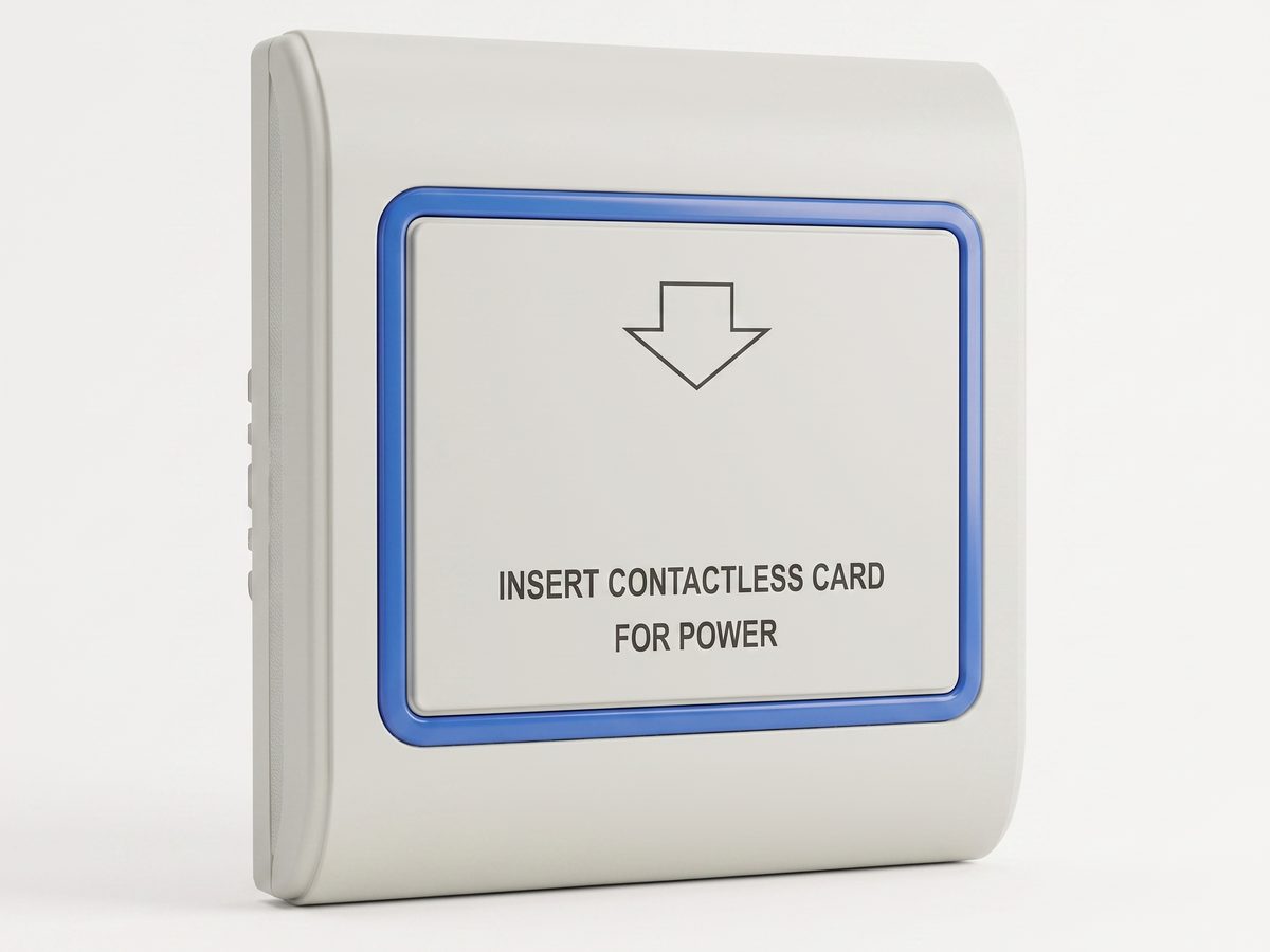
RFID 取电开关 — 13.56MHz 非接触式客房取电控制
RFID 取电开关采用 13.56MHz 非接触感应,客人轻触感应区即可取电,无需插卡槽。兼容酒店门锁系统,CE RoHS 认证,OEM/ODM 源头供应商。
当前页面已经把它作为下一步推荐内容直接指向。
相关解决方案
3相关文章
3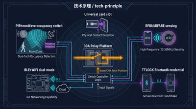
酒店取电开关五大控制模型详解:通用、RFID、TTLOCK、BLE 与占用传感器选型指南
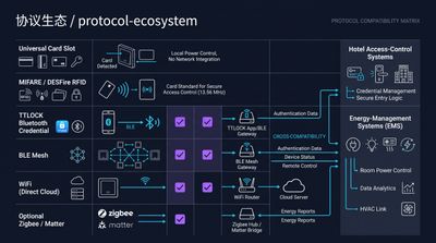
酒店取电开关涵盖通用、RFID、TTLOCK、BLE 与占用传感器五大型号。本指南详解取电开关、插卡取电开关等核心词对应的产品家族,对比各模型读卡规则、组网方式与适用场景,助您按现有门锁系统精准选型,无需换卡即可实现客房节能 25-40%。
它服务于同一产品语境:酒店取电开关 — 客房电源智能控制方案。
RFID 与 NFC 酒店取电开关选型完全指南:125kHz 与 13.56MHz 卡技术核心差异
酒店取电开关选 RFID 还是 NFC?本质是卡技术家族与手机协议的区别:125kHz 与 13.56MHz RFID(MIFARE、Temic)是客房取电主流,支持扇区密钥绑定仅识自家房卡;NFC 只是手机模拟卡的贴近协议。文章对比读卡原理、防串用能力与选型建议,助工程商按现有门锁卡型精准决策。
它服务于同一产品语境:酒店取电开关 — 客房电源智能控制方案。
什么是酒店取电开关?核心工作原理、四大主流产品类型及客房节能 25-40% 的详细完整深度全解析
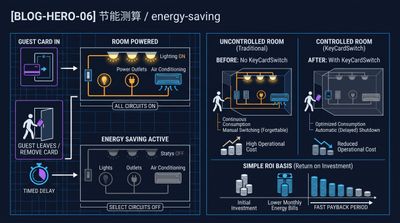
酒店取电开关插卡通电、取卡断电,客房节能 25-40%。对比通用型、RFID 型、TTLOCK 兼容型、BLE 智能型四大模式差异,涵盖 30A 继电器、15 秒延时、86 型底盒安装等关键参数,助您按现有刷卡系统精准选型,无需联网即可部署。
它服务于同一产品语境:酒店取电开关 — 客房电源智能控制方案。
与我们的工程师对接您的酒店项目
告知我们房间数量、吊顶类型、协议偏好,24 业务小时内返回打样方案和报价。
- 把泛化知识内容继续引向具体产品或应用场景讨论。
- 当客户要谈价格、图纸、MOQ 或项目节奏时,直接进入 RFQ。
- 同时保留直接联系入口,便于快速澄清问题和内部转交。