酒店取电开关门锁集成:实操指南
了解酒店取电开关如何与 Onity、VingCard、Assa Abloy、SALTO 门锁配合工作,涵盖卡片、布线、无线门锁及改造协调要点。
酒店取电开关门锁集成通常是一个协调问题,而非直接的电子连接。门锁读卡器在入口处验证凭证,而客房开关在客人在室内出示有效卡片后控制选定负载。在大多数项目中,两个设备均可接受相同的卡片格式,而无需共享数据、固件或网络。开关按卡片技术、电压、负载和触点排列选型;门锁按其凭证系列、锁芯硬件、访问规则及离线或在线架构选型。因此,成功的设计必须在安装前确认卡片兼容性、电气隔离、安装位置及调试责任。本指南解释常见酒店门锁系列如何与取电开关配合工作、何时无需集成布线、无线门锁如何改变改造序列,以及业主、门锁供应商、电气承包商和开关供应商如何避免交接纠纷。
酒店取电开关门锁集成架构
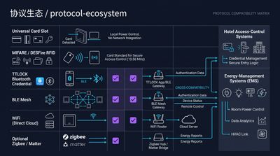
酒店取电开关门锁集成使用两个协调但通常独立的系统:门锁授权入室,而客房开关启用选定电气负载。开关可读取接触式卡片或 RFID 凭证,门锁可使用编程凭证,但共用卡片不意味着存在数据线缆或共同控制器。典型受控负载包括照明、插座、风机盘管启用及控制大回路的接触器。门锁负责门禁、隐私、机械释放和凭证规则。开关负责其继电器、定时及客房回路。这种边界划分提高了韧性:开关故障不应阻碍入室,门锁电池问题不应导致客房供电系统失控。架构图应显示两个设备、其供电、其回路及确切的客人操作序列。若业主要求门信号、中央监控或自动占用逻辑,属于额外的控制项目,必须单独指定。
选品前先区分功能
客房供电开关通常置于入口附近,方便客人进室时找到。其输出可接照明场景、插座组,或控制大负载的接触器。具体回路布置属于电气设计范畴,开关供应商应收到最终的电压和电流清单。门锁读卡器通常安装在门外侧,针对门禁、耐候、安防及电池维护进行优化。将供电开关置入该安防链路可能造成不可取的单点故障。清晰的分离可让门锁在客房供电控制维修期间保持门禁功能。
规范书中的集成措辞可能产生误导。在某项目中,集成可能指一张卡在两个读卡器通用;在另一项目中,可能指直接干接点、控制器或软件事件。这些范围实质不同。用白话写明预期序列:出示卡片、启用选定负载、取走卡片、延时、保留必要回路。然后说明门读卡器是否必须发送信号。若不需要,弱电图纸应显示两个独立系统及仅有的共同调试测试。
除非专门为该目的设计并测试,否则不应将开关用作安防指示器。卡片留在取电座并不证明授权客人在场。同样,灯光熄灭也不证明客房无人。此区别对客房服务、维护、应急响应及无障碍至关重要。业主应将开关描述为供电控制设备,将门禁决策保留在门锁系统内。
客房标准应含单线图、卡片样品照片、安装详图及操作序列。应标识必须保持带电的回路,如制冷、生命安全设备或适用的特定充电插座。在跨楼层复制前,与门锁供应商和电气工程师复核标准。这一小步骤可防止品牌兼容的读卡器被安装在不合适的回路上。
酒店取电开关门锁集成与共用卡片
共用卡片指一张实体客人凭证可同时被门锁和客房开关接受,但不意味着两设备电子集成。卡片必须呈现各设备支持的技术和读取行为。部分开关响应卡片物理存在,不验证编码的客人身份;另一些专为特定 RFID 系列设计,可能拒绝不兼容芯片。门锁可能使用加密扇区、编程序列号或专有凭证配置。订货前,获取门锁供应商的凭证规格,询问开关供应商可读取哪些卡片类型。测试实际卡片库存,含钥匙套和印刷覆膜,因厚度和天线位置可能影响插入或读取距离。决策应在采购前记录,因为读卡器、门锁和客房供电回路各自正确,仍可能作为客人工作流而失败。样板间测试是实证。
卡片技术才是真正接口
卡片外观相似不代表技术兼容。两张卡片印刷图案相同,可能使用不同芯片、频率、内存布局或读取行为。索要卡片料号、技术、适用工作频率,以及门锁是否在受保护扇区编码凭证。要求开关供应商用相同术语说明支持的系列。若供应商无法说明读取方式,采购前要求样品测试。
开关可能刻意比门锁宽容。部分酒店节能开关检测卡片物理形状或宽泛 RFID 存在,而门锁核查凭证是否获特定门和时间的授权。这让客房供电体验便捷,但也意味着员工卡、过期卡或其他兼容令牌可能激活开关。运营策略应决定该行为是否可接受。若项目需身份验证,可指定更严格的读卡器。
卡套、钥匙扣、移动凭证、金属钱包需显性测试。卡套可能阻碍接触式卡片完全就位或改变 RFID 天线距离。钥匙扣可能被门锁接受但不适配插槽式开关。手机凭证可能解锁无线门锁,完全无需出示卡片。若业主想要手机开门并自动供电,那是独立的用户体验和控制需求,非门锁兼容性的自动结果。
项目档案保留受控卡片样品。标注技术、发行日期、预期用途,工厂验收和现场验收时使用。勿用本地印刷厂视觉相似的卡片替代。酒店日后更换门锁凭证时,即使面板和布线未变,开关行为也必须重测。
同卡不同权
门锁可拒绝挂失或过期卡,而宽泛感应开关仍响应。这不一定是缺陷,而是功能差异导致。项目组应决定客房开关接受所有兼容令牌、仅窄范围卡片系列、还是经验证凭证。每个选项影响读卡器成本、客人体验和服务流程。将决策写入客房标准,而非留给安装工决定。
酒店取电开关门锁集成与 Onity 门锁
Onity 门锁与酒店取电开关通常作为独立客房设备并行工作。实际问题不在于开关是否为 Onity 品牌,而在于其是否读取该物业门锁使用的凭证格式。Onity 部署可能包含不同代际的读卡器、卡片和编码实践,故项目应核实安装的门锁型号和卡片技术,而非仅凭品牌名。门锁通常在门侧处理门禁决策;开关可用兼容卡片作为客房存在触发器,或仅检测卡片令牌。实现该基本行为通常无需门锁到开关的数据线。改造期间,门锁供应商负责门硬件、读卡器编程和门禁测试,电气承包商负责开关回路布线。
Onity 协调问题
向 Onity 承包商询问确切读卡器系列、卡片样品、适用凭证频率,以及员工卡是否区别于客人卡。询问开关供应商其读卡器是否检测相同技术,以及是验证身份还是仅感应存在。记录于兼容性矩阵。避免断言所有 Onity 门锁和所有开关共享通用接口,因门锁代际和卡片配置各异。
联合样板间测试确认客人、客房服务和应急卡按预期工作。在门锁和开关测试授权客人卡。测试物理相似但未获批的卡。测试取卡、延时和必要回路。Onity 安装工签署门禁部分,电工签署供电部分。单一合并清单让客人工作流可视,且不将错误责任归于错误工种。
酒店取电开关门锁集成与 VingCard 系统
VingCard 门锁系统与酒店取电开关可部署于同一客房,前提是开关按现场卡片系列和电气设计选型。VingCard 是产品生态而非通用卡片规格,物业可能有不同代际读卡器或凭证配置。批准开关前,索要确切卡片技术,而非仅门锁品牌。门锁读卡器仍负责走廊门门禁,而开关按客房供电设计控制照明、插座、风机盘管启用或接触器。此布置通常无共用通讯线缆。关键协调点为卡片呈现、墙盒尺寸、回路分组,以及仅检测插入与验证凭证的开关之别。决策应在采购前记录,因为读卡器、门锁和客房供电回路各自正确,仍可能作为客人工作流而失败。样板间测试是实证。
VingCard 项目工作流
样板间应含实际 VingCard 发行卡片、选定面板和最终电气负载,免得安装工在客房完工后发现不兼容。确认卡片在开关处须插入、轻触还是靠近。确认卡套是否改变读取行为。确认开关触点额定值适配负载或选定接触器线圈。门锁安装工不应被要求批准强电布线,电工不应被要求改变凭证编程。
物业有多栋楼或分期装修时,按阶段建卡片清单。新 VingCard 读卡器可能用不同于旧楼的凭证系列。相同印刷图案可能掩盖差异。用各阶段卡片测试各拟用开关。若一开关须支持多卡片系列,获取书面支持细节并测试所有系列,而非假设通用读卡器。
酒店取电开关门锁集成与 Assa Abloy 门锁
Assa Abloy 酒店门锁在双方均支持物业选定的凭证格式时,可与兼容取电开关并行工作。同卡结果取决于卡片技术、读卡器配置和开关感应方式;非仅凭 Assa Abloy 品牌保证。确认门锁用接触式卡片、13.56 MHz RFID 凭证还是其他格式,并询问员工凭证如何区别于客人卡。门锁通常仍为门侧电池供电或本地供电门禁设备。客房开关仍为室内低压控制和市电负载安装的一部分。保持边界清晰可避免门与开关间不必要的线缆。决策应在采购前记录,因为读卡器、门锁和客房供电回路各自正确,仍可能作为客人工作流而失败。样板间测试是实证。
Assa Abloy 改造核查
装修时,在一份客房清单记录门号、门锁型号、卡片样品、开关位置。然后由门锁安装工和电工在场,测试入室、供电激活、取卡延时和故障安全行为。核实拟用开关适配现有墙盒,不与读卡器、温控器、行李凳或门饰条冲突。若门锁为无线或电池供电,勿推断客房开关可接收入室事件。
规范书应区分卡片兼容性与官方合作。卡片格式受支持且设备通过项目测试时,准确说开关与门锁并行工作。除非责任制造商文档证明该确切布置,否则不准确暗示联合产品、认证互操作或专有数据链路。
酒店取电开关门锁集成与 SALTO 门锁
SALTO 门禁系统与酒店取电开关作为相邻功能兼容,前提是开关读卡器支持 SALTO 安装使用的卡片技术。SALTO 项目因凭证系列、门锁硬件、运营模式而异,故卡片样品和读卡器规格比通用品牌假设更有用。客人可用一张卡开门和取电,但开关可能仅检测卡片存在而非核查权限。该区别应向业主解释:取走卡片可关断客房回路,即使该卡在门锁处已无效。基本客房供电控制不要求开关连接门锁、控制器或软件服务。决策应在采购前记录,因为读卡器、门锁和客房供电回路各自正确,仍可能作为客人工作流而失败。样板间测试是实证。
SALTO 调试边界
协调开关位置与开门方向、行李移动、无障碍净空,同时 SALTO 承包商验证门锁开向、审计行为、访问凭证。用物业真实卡片和例外卡片调试两系统。确认卡片呈现舒适、卡套不遮挡读卡器、开关不响应非预期附近令牌。
业主应决定客房服务卡、维护卡、应急凭证如何表现。检测兼容令牌的开关可能为员工通电,即使 SALTO 门锁应用不同门禁规则。该行为可接受,但须声明。若不可接受,指定更具选择性的读卡器并用实际凭证集测试。
酒店取电开关门锁集成布线决策
标准安装中,酒店取电开关门锁集成不需客房开关与门锁间的数据线缆。开关接入客房指定供电控制回路,负载超额定时常通过继电器或接触器。门锁按自有硬件设计安装供电,常用电池或专用门禁供电。共用卡片提供人工工作流链接,非通讯链接。当业主想要中央控制器、门位信号、硬线应急释放或自定义逻辑序列时,集成布线成为单独设计需求。决策应在采购前记录,因为读卡器、门锁和客房供电回路各自正确,仍可能作为客人工作流而失败。样板间测试是实证。
何时真正需要线缆
此类需求应在电气和弱电图纸标明线缆类型、端接、电源、隔离、测试责任。切勿仅因端子外观相似便将门锁输出接开关端子。通电前确认电压、电流、触点类型、极性及当地规范要求。干接点、有源输出、通讯总线非可互换接口。
典型开关回路含保护装置、开关或继电器、接触器线圈、一或多受控回路。门锁有自带电池、读卡器布线或门禁供电。按工程师图纸及适用当地规则,将强电导体、弱电导体、门硬件线缆分路布线端接。开关供应商可说明端子极限,但项目电气工程师批准安装方法。
布线对比
| 集成维度 | 独立客房开关与门锁 | 直接信号设计 | 仅共用卡片 |
|---|---|---|---|
| 门到开关数据线 | 通常不需要 | 指定时需要 | 不需要 |
| 主要接口 | 卡片呈现与独立供电回路 | 干接点、控制器或定义总线 | 相同卡片技术 |
| 门禁决策 | 门锁 | 门锁或批准控制器 | 门锁 |
| 客房供电决策 | 开关逻辑 | 工程控制逻辑 | 开关逻辑 |
| 调试主导 | 电工配合门锁样品 | 控制工程师加双工种 | 电工与门锁供应商 |
| 主要风险 | 错误卡片或负载假设 | 接口或隔离错误 | 不同卡片格式 |
酒店取电开关门锁集成与无线门锁
无线酒店门锁通常简化物理改造,因门读卡器无需线缆连接客房开关。无线门锁仍需凭证计划,开关仍需客房供电回路和合适卡片读卡器。因设备不交换实时信号,无线门锁不自动告知开关客人已入室。开关响应自身卡片呈现、定时器或配置感应行为。这对简单客房工作流可接受,但业主应理解边缘情况:客人用手机凭证入室、员工用不同卡片、退房后卡片留在开关内。决策应在采购前记录,因为读卡器、门锁和客房供电回路各自正确,仍可能作为客人工作流而失败。样板间测试是实证。
无线改造序列
将无线门锁调试、电池维护、无线勘测、开关安装作为并行工作包协调。样板间应测试实际无线门锁凭证、开关卡片响应、选定负载控制序列,而不暗示一设备监督另一设备。分别检查对门、锁舌运动、电池更换净空、信号状况,独立于客房电气测试。
无线门禁减少一类布线但不消除协调。电工仍需通往开关的安全路径,门锁承包商仍需进入门和门框。避免将开关置于金属门、柜体、装饰面板遮蔽 RFID 读卡器处。在成品墙面和家具下测试,而非仅未完工样板间。
酒店取电开关门锁集成改造协调
改造成功源于采购前对现有门锁系统、新开关、客房布线的勘测。从逐间清单起步:门锁品牌型号、卡片技术、开关开孔、供电电压、受控负载、配电箱空间、进场日期。邀请门锁承包商、电气承包商、总承包商、开关供应商批准一间样板间。门锁承包商确认卡片和门禁行为;电气承包商确认回路拓扑和隔离;开关供应商确认读卡器兼容性和端子极限。约定谁供测试卡片、谁签功能清单。除非有文档变更要求,保留门硬件和门锁固件。决策应在采购前记录,因为读卡器、门锁和客房供电回路各自正确,仍可能作为客人工作流而失败。样板间测试是实证。
改造接口矩阵
| 确认项 | 门锁承包商 | 电气承包商 | 开关供应商 | 业主或总包 |
|---|---|---|---|---|
| 安装门锁型号 | 确认 | 记录 | 复核卡片要求 | 批准进度 |
| 实际卡片样品 | 提供 | 测试 | ||
| Hotel key card switch door lock integration is usually a coordination problem rather than a direct electronic connection. The lock reader verifies a credential at the entrance, while the room switch controls selected loads after a guest presents an approved card inside the room. In most projects, both devices can accept the same card format without sharing data, firmware, or a network. The switch is specified by card technology, voltage, load, and contact arrangement; the lock is specified by its credential family, cylinder hardware, access rules, and offline or online architecture. A successful design therefore confirms card compatibility, electrical separation, mounting position, and commissioning responsibilities before installation. This guide explains how common hotel lock families work alongside key card switches, when integrated wiring is unnecessary, how wireless locks change the retrofit sequence, and how owners, lock vendors, electrical contractors, and switch suppliers can avoid handover disputes. |
Hotel key card switch door lock integration architecture
Hotel key card switch door lock integration uses two coordinated but normally independent systems: the door lock grants entry, while the room switch enables selected electrical loads. A switch may read a contact card or RFID credential, and a lock may use a programmed credential, but a shared card does not imply a data cable or common controller. Typical controlled loads include lighting, sockets, fan-coil enable, and a contactor for a larger circuit. The lock remains responsible for access, privacy, mechanical release, and credential rules. The switch remains responsible for its relay, timing, and room circuit. This boundary improves resilience because a switch fault should not prevent entry and a lock battery issue should not leave the room power system uncontrolled. Architecture drawings should show both devices, their supplies, their circuits, and the exact guest sequence. If an owner requests a door signal, central supervision, or automatic occupancy logic, that is an additional controls project and must be specified separately.
Separate functions before selecting products
A room power switch is commonly placed near the entrance so the guest can find it while entering. Its output may feed lighting scenes, socket groups, or a contactor that controls a larger load. The exact circuit arrangement belongs on the electrical design, and the switch supplier should receive the final voltage and current schedule. A door lock reader normally sits on the door exterior and is optimized for access, weather exposure, security, and battery service. Placing a power switch in that security chain can create an undesirable single point of failure. A clean separation lets the lock keep its access function during a room power-control repair.
Integration language can be misleading in specifications. In one project, integration may mean one card works in two readers. In another, it may mean a direct dry contact, a controller, or a software event. These are materially different scopes. Write the intended sequence in plain language: present card, enable selected loads, remove card, apply delay, retain essential circuits. Then state whether the door reader must send any signal. If it does not, the low-voltage drawings should show two independent systems and a shared commissioning test only.
The switch should not be used as a security indicator unless it has been specifically engineered and tested for that purpose. A card left in a holder does not prove that the authorized guest is present. Likewise, a light turning off does not prove that the room is vacant. This distinction matters for housekeeping, maintenance, emergency response, and accessibility. Owners should describe the switch as a power-control device and keep door access decisions within the lock system.
A room standard should include a one-line diagram, a card sample photograph, a mounting detail, and a sequence of operation. It should identify circuits that must remain live, such as refrigeration, life-safety equipment, or selected charging outlets where applicable. Review the standard with the door lock vendor and the electrical engineer before repeating it across floors. This small approval step prevents a brand-compatible reader from being installed on an unsuitable circuit.
Hotel key card switch door lock integration and shared cards
A shared card means one physical guest credential can be accepted by both the door lock and the in-room switch, but it does not mean the two devices are electronically integrated. The card must present a technology and reading behavior that each device supports. Some switches respond to a card's physical presence and do not validate the encoded guest identity; others are designed for a specific RFID family and may reject an incompatible chip. A lock may use encrypted sectors, a programmed serial number, or a proprietary credential profile. Before ordering, obtain the lock supplier's credential specification and ask the switch supplier which card types it reads. Test the actual card stock, including key sleeves and printed overlays, because thickness and antenna position can affect insertion or read distance. The decision should be recorded before procurement, because a card reader, door lock, and room power circuit can each be correct on its own while still failing as a guest workflow. A sample-room test is practical proof.
Card technology is the real interface
Visual similarity between cards is not evidence of technical compatibility. Two cards may have the same printed artwork while using different chips, frequencies, memory layouts, or reader behaviors. Ask for the card part number, technology, operating frequency where applicable, and whether the lock encodes credentials in a protected sector. Ask the switch supplier to state its supported families in the same terminology. If a supplier cannot identify the reading method, require a sample test before purchase.
The switch may be intentionally less selective than the lock. Some hotel energy switches detect a physical card shape or a broad RFID presence, while the lock checks whether a credential is authorized for a particular door and time. That can make the room power experience convenient but also means a staff card, expired card, or another compatible token might activate the switch. The operating policy should decide whether that behavior is acceptable. A stricter reader can be specified if the project needs identity validation.
Card sleeves, key fobs, mobile credentials, and metal wallets deserve explicit testing. A sleeve can prevent a contact card from seating fully or change the distance to an RFID antenna. A fob may be accepted by the door but not fit a slot-style switch. A phone credential may unlock a wireless door without presenting a card at all. If the owner wants phone-based entry and automatic room power, that is a separate user-experience and controls requirement, not an automatic result of lock compatibility.
Keep a controlled card sample in the project records. Label it with technology, issue date, and intended use, and use it during factory and site acceptance tests. Do not substitute a visually similar card from a local printer. When a hotel changes lock credentials later, the switch behavior must be retested even if the faceplate and wiring remain unchanged.
Same card, different authorization
A lock can reject a lost or expired card while a broad-presence switch still responds to it. That is not necessarily a defect; it is a result of different functions. The project team should decide whether the room switch should accept all compatible tokens, only a narrow card family, or a validated credential. Each option affects reader cost, guest experience, and service procedures. Put the decision in the room standard rather than leaving it to an installer.
Hotel key card switch door lock integration with Onity locks
Onity locks and a hotel key card switch generally work alongside one another as separate room devices. The practical question is not whether the switch is branded Onity, but whether it reads the same credential format used by the property's door locks. An Onity deployment may include different generations of readers, cards, and encoder practices, so a project should verify the installed lock model and card technology rather than rely on the brand name alone. The door lock normally handles access decisions at the door; the switch can use a compatible card as a room-presence trigger or simply detect a card token. No lock-to-switch data cable is normally required for that basic behavior. During a retrofit, keep the lock vendor responsible for door hardware, reader programming, and access testing, while the electrical contractor handles switch circuit wiring.
Onity coordination questions
Ask the Onity contractor for the exact reader family, card sample, credential frequency where applicable, and whether staff cards differ from guest cards. Ask the switch supplier whether its reader detects the same technology and whether it validates identity or merely senses presence. Record the answer in a compatibility matrix. Avoid saying that every Onity lock and every switch share a universal interface, because lock generations and card configurations differ.
A joint sample-room test confirms that guest, housekeeping, and emergency cards behave as intended. Test an authorized guest card at the door and in the switch. Test a card that is physically similar but not approved. Test card removal, delay, and essential circuits. The Onity installer should sign the access portion and the electrician should sign the power portion. A single combined checklist keeps the guest workflow visible without assigning the wrong trade responsibility.
Hotel key card switch door lock integration with VingCard systems
VingCard lock systems and hotel key card switches can be deployed in the same room when the switch is selected for the site's card family and electrical design. VingCard is a product ecosystem rather than a universal card specification, and properties may have different reader generations or credential configurations. Ask for the exact card technology, not only the lock brand, before approving a switch. The lock reader can remain responsible for access at the corridor door, while the switch controls lighting, sockets, fan-coil enable, or a contactor according to the room power design. This arrangement normally uses no shared communications cable. The important coordination points are card presentation, wall-box dimensions, circuit grouping, and the distinction between a switch that merely detects insertion and one that validates a credential. The decision should be recorded before procurement, because a card reader, door lock, and room power circuit can each be correct on its own while still failing as a guest workflow. A sample-room test is practical proof.
VingCard project workflow
A mock-up should include the actual VingCard-issued card, the selected faceplate, and the final electrical load so installers do not discover incompatibility after rooms are finished. Confirm whether a card must be inserted, tapped, or held near the switch. Confirm whether a sleeve changes the reading behavior. Confirm that the switch's contact rating is suitable for the load or for the selected contactor coil. The lock installer should not be asked to approve mains wiring, and the electrician should not be asked to change credential programming.
When a property has several buildings or renovation phases, make a card inventory by phase. A new VingCard reader may use a different credential family from an older building. The same printed artwork can hide this difference. Test each phase's cards with each proposed switch. If one switch must support multiple card families, obtain written support details and test all families rather than assuming a universal reader.
Hotel key card switch door lock integration with Assa Abloy locks
Assa Abloy hotel locks can work alongside a compatible key card switch when both devices support the credential format chosen by the property. The same-card outcome depends on card technology, reader configuration, and the switch's sensing method; it is not guaranteed by the Assa Abloy name alone. Confirm whether the lock uses a contact card, 13.56 MHz RFID credential, or another format, and ask how staff credentials differ from guest cards. The lock usually remains a battery-powered or locally powered access device at the door. The room switch remains part of the low-voltage control and mains-load installation inside the room. Keeping those boundaries clear avoids an unnecessary cable between the door and the switch. The decision should be recorded before procurement, because a card reader, door lock, and room power circuit can each be correct on its own while still failing as a guest workflow. A sample-room test is practical proof.
Assa Abloy retrofit checks
For a renovation, record door numbers, lock models, card samples, and switch locations in one room schedule. Then test entry, power activation, card removal delay, and fail-safe behavior with the lock installer and electrician present. Verify that the proposed switch fits the existing wall box and does not conflict with a reader, thermostat, luggage bench, or door trim. If the door lock is wireless or battery powered, do not infer that the room switch can receive an entry event.
The specification should distinguish card compatibility from official cooperation. It is accurate to say that the switch works alongside a lock when the card format is supported and the devices pass the project test. It is not accurate to imply a joint product, certified interoperability, or a proprietary data link unless the responsible manufacturers have documented that exact arrangement.
Hotel key card switch door lock integration with SALTO locks
SALTO access systems and hotel key card switches are compatible as neighboring functions when the switch reader supports the card technology used by the SALTO installation. SALTO projects can vary by credential family, lock hardware, and operating model, so the card sample and reader specification are more useful than a generic brand-level assumption. A guest may use one card for the door and room switch, yet the switch may only detect the card's presence rather than check its permissions. That distinction should be explained to the owner: removing a card can turn off a room circuit even if the card is no longer valid at the door. Basic room power control does not require the switch to connect to the lock, a controller, or a software service. The decision should be recorded before procurement, because a card reader, door lock, and room power circuit can each be correct on its own while still failing as a guest workflow. A sample-room test is practical proof.
SALTO commissioning boundaries
Coordinate the switch location with door swing, luggage movement, and accessibility clearances, while the SALTO contractor validates lock handing, audit behavior, and access credentials. Commission both systems using the property's real cards and exception cards. Confirm that the card can be presented comfortably, that a sleeve does not block the reader, and that the switch does not respond to an unintended nearby token.
The owner should decide how housekeeping cards, maintenance cards, and emergency credentials behave. A switch that detects a compatible token may energize a room for a staff member even when the SALTO lock would apply a different access rule. That behavior can be acceptable, but it must be stated. If it is not acceptable, specify a more selective reader and test it with the actual credential set.
Hotel key card switch door lock integration wiring decisions
In a standard installation, hotel key card switch door lock integration does not require a data cable between the room switch and the door lock. The switch is wired into the room's designated power-control circuit, commonly through a relay or contactor when the load exceeds the switch rating. The lock is installed and powered according to its own hardware design, often with batteries or a dedicated access-control supply. A shared card provides a human workflow link, not a communications link. Integrated wiring becomes a separate design request when the owner wants a central controller, a door-position signal, a hardwired emergency release, or a custom logic sequence. The decision should be recorded before procurement, because a card reader, door lock, and room power circuit can each be correct on its own while still failing as a guest workflow. A sample-room test is practical proof.
When a cable is actually justified
Those requirements should be shown on electrical and low-voltage drawings with cable type, termination, power source, isolation, and testing responsibility. Never connect a lock output to a switch terminal simply because the terminals look similar. Confirm voltage, current, contact type, polarity, and local code requirements before energizing any circuit. A dry contact, powered output, and communication bus are not interchangeable interfaces.
A typical switch circuit may contain a protective device, the switch or relay, a contactor coil, and one or more controlled circuits. The lock may have its own battery, reader wiring, or access-control supply. Keep mains conductors, low-voltage conductors, and door hardware cabling routed and terminated according to the engineer's drawings and applicable local rules. The switch supplier can explain terminal limits, but the project electrical engineer approves the installation method.
Wiring comparison
| Integration dimension | Independent room switch and lock | Direct signal design | Shared card only |
|---|---|---|---|
| Door-to-switch data cable | Normally not required | Required if specified | Not required |
| Main interface | Card presentation and separate power circuits | Dry contact, controller, or defined bus | Same card technology |
| Access decision | Door lock | Door lock or approved controller | Door lock |
| Room power decision | Switch logic | Engineered control logic | Switch logic |
| Commissioning lead | Electrician with lock vendor sample | Controls engineer plus both trades | Electrician and lock vendor |
| Main risk | Wrong card or load assumption | Incorrect interface or isolation | Different card formats |
Hotel key card switch door lock integration for wireless locks
Wireless hotel locks usually simplify the physical retrofit because the door reader does not need a cable to the in-room switch. The wireless lock still needs a credential plan, while the switch needs a room power circuit and a suitable card reader. Since the devices do not exchange a live signal, a wireless door lock does not automatically tell the switch that a guest entered. The switch reacts to its own card presentation, timer, or configured sensing behavior. This can be acceptable for a simple guest-room workflow, but owners should understand edge cases such as a guest entering with a phone credential, a staff member using a different card, or a card being left in the switch after checkout. The decision should be recorded before procurement, because a card reader, door lock, and room power circuit can each be correct on its own while still failing as a guest workflow. A sample-room test is practical proof.
Wireless retrofit sequence
Coordinate wireless lock commissioning, battery access, radio survey, and switch installation as parallel work packages. The room mock-up should test the actual wireless lock credential, the switch's card response, and the selected load-control sequence without implying that one device supervises the other. Check door alignment, latch movement, battery replacement clearance, and signal conditions separately from the room's electrical test.
Wireless access reduces one category of cabling but does not eliminate coordination. The electrician still needs a safe route to the switch, and the lock contractor still needs access to the door and frame. Avoid placing a switch where a metal door, cabinet, or decorative panel shields an RFID reader. Test with the finished wall and furniture, not only with an unfinished mock-up.
Hotel key card switch door lock integration retrofit coordination
A retrofit succeeds when the existing lock system, new switch, and room wiring are surveyed before procurement. Start with a room-by-room inventory: door lock brand and model, card technology, switch cut-out, supply voltage, controlled loads, distribution-board space, and access dates. Invite the lock contractor, electrical contractor, general contractor, and switch supplier to approve one sample room. The lock contractor confirms cards and access behavior; the electrical contractor confirms circuit topology and isolation; the switch supplier confirms reader compatibility and terminal limits. Agree who supplies cards for testing and who signs the functional checklist. Preserve door hardware and lock firmware unless a documented change is required. The decision should be recorded before procurement, because a card reader, door lock, and room power circuit can each be correct on its own while still failing as a guest workflow. A sample-room test is practical proof.
Retrofit interface matrix
| Item to confirm | Door lock contractor | Electrical contractor | Switch supplier | Owner or general contractor |
|---|---|---|---|---|
| Installed lock model | Confirm | Record | Review card requirement | Approve schedule |
| Actual card sample | Provide | Test | Test reader | Approve guest workflow |
| Door hardware | Install and test | Avoid changes | No responsibility | Coordinate access |
| Room circuit | Record interface only | Design and wire | State terminal limits | Approve loads |
| Sample room | Access test | Electrical test | Reader test | Sign acceptance |
| Room release | Sign lock result | Sign circuit result | Sign product result | Close defects |
If the renovation changes cards, test existing doors before distributing new credentials. Sequence dusty demolition before installing readers and faceplates, then protect finished surfaces during cable pulling. A controlled pilot reduces repeated room entry and exposes card, mounting, and load issues while corrections are still inexpensive. Keep a photographic record of the approved location so later rooms do not drift from the standard.
Managing trade timing
The lock contractor may finish doors weeks before the electrician reaches the final room circuits. The switch supplier may be asked for an answer without seeing the actual card. The owner may approve a brand based on a previous property with a different credential family. A written interface matrix resolves these gaps. It lists device, purpose, card input, power source, cable requirement, responsible trade, test method, and acceptance evidence. It also identifies what is explicitly not included, such as direct lock control or an assumption that every credential type will activate power.
Hotel key card switch door lock integration commissioning checklist
Commissioning should prove the complete guest workflow while keeping access control and power control tests separately traceable. For each room, record the lock model, switch model, card type, circuit identifier, and approved load. Test a valid guest card at the door and at the switch, then test an invalid or incompatible card. Remove the card and verify the configured delay, while checking that essential circuits remain powered if the design requires them. Confirm the switch does not nuisance-trigger from a wallet, metal sleeve, or nearby card. Verify relay or contactor operation under the real load, not only with a lamp on a workbench. The decision should be recorded before procurement, because a card reader, door lock, and room power circuit can each be correct on its own while still failing as a guest workflow. A sample-room test is practical proof.
Functional test sequence
- Inspect the installed faceplate, card orientation, labels, and wall-box fit.
- Verify supply voltage and protective-device identification before inserting a card.
- Present the approved guest card at the door and record the access result.
- Present the same card at the switch and record which circuits change state.
- Remove the card and measure the configured delay and final state.
- Repeat with an approved staff card, maintenance card, and incompatible card.
- Check essential circuits, bypass functions, contactor operation, and labeling.
- Record defects by room and assign each defect to one responsible trade.
The lock contractor should test mechanical release, privacy function, emergency procedure, and credential lifecycle; the electrician should test insulation, protective devices, polarity, and labeling. Jointly record exceptions, photographs, and corrective actions. A signed room schedule is more valuable than a generic statement that the brands are compatible. If the card opens the door but fails at the switch, investigate the card technology before changing wiring. If the switch works but the load remains energized, investigate the electrical circuit before changing lock programming.
Hotel key card switch door lock integration procurement guide
Procurement documents should describe an application and interface boundary rather than demand an unsupported promise of universal compatibility. Specify the target use case, the card technology, switch mounting style, supply voltage, controlled load, contact rating, faceplate finish, and required removal delay. Ask bidders to state which card formats they read and whether the reader detects presence, validates a serial number, or uses another method. Request a physical sample and a written wiring diagram for approval. The decision should be recorded before procurement, because a card reader, door lock, and room power circuit can each be correct on its own while still failing as a guest workflow. A sample-room test is practical proof. The decision should be recorded before procurement, because a card reader, door lock, and room power circuit can each be correct on its own while still failing as a guest workflow. A sample-room test is practical proof.
Questions for a quotation
For the door lock, collect the exact installed model and credential specification from the lock contractor. A brand list such as Onity, VingCard, Assa Abloy, or SALTO is useful for coordination but cannot replace a card-format test. Include responsibility for sample-room commissioning, spare units, labels, manuals, and warranty support. Separate compliance evidence that actually applies to the supplied product from marketing claims, and have the project team verify local electrical and fire requirements.
Ask whether the switch has a configurable delay, whether a contactor is recommended for the planned load, and what happens after a power interruption. Ask how cards are presented and whether a card sleeve affects operation. Ask whether the product accepts one credential family or several. Ask for dimensional drawings before cutting walls. These questions are more useful than a generic statement that a switch is universal.
Hotel key card switch door lock integration troubleshooting
Most failures in a combined room workflow come from assumptions about cards, circuits, or responsibilities rather than from a mysterious lock protocol. If a switch does not respond, first compare the physical card with the approved sample and check insertion direction, reader type, and power supply. If it responds intermittently, inspect card thickness, antenna alignment, faceplate pressure, and nearby electromagnetic noise. If the switch works but loads remain on, check relay wiring, contactor coil voltage, bypass switches, and the intended timer. The decision should be recorded before procurement, because a card reader, door lock, and room power circuit can each be correct on its own while still failing as a guest workflow. A sample-room test is practical proof. The decision should be recorded before procurement, because a card reader, door lock, and room power circuit can each be correct on its own while still failing as a guest workflow. A sample-room test is practical proof.
If a door opens but the switch rejects the card, the two readers may use different credential technologies even though the card looks identical. If a wireless lock works inconsistently, investigate battery condition, radio environment, and door alignment separately from the switch. Keep a fault log by room and reproduce issues with known-good cards. Do not change lock programming, switch terminals, or protective devices simultaneously; isolate one variable, document the result, and obtain the responsible vendor's approval before altering a production room.
Hotel key card switch door lock integration design decisions
The final design decision is usually a balance between a familiar guest experience and a maintainable technical boundary. Using one card for the door and room switch reduces what guests carry, but it requires a verified shared card format and a clear explanation of what the switch actually checks. Using separate credentials can simplify technical compatibility but may create operational friction. A basic switch with no data link is easier to install and troubleshoot; a networked control design may add functions but requires a separately engineered architecture and service responsibility. The decision should be recorded before procurement, because a card reader, door lock, and room power circuit can each be correct on its own while still failing as a guest workflow. A sample-room test is practical proof. The decision should be recorded before procurement, because a card reader, door lock, and room power circuit can each be correct on its own while still failing as a guest workflow. A sample-room test is practical proof.
For every option, ask what happens during a flat card battery, an invalid card, a lost credential, a power outage, a room change, and a maintenance visit. Document those answers in the room standard before issuing purchase orders. Make the access system the authority for entry and the electrical design the authority for loads. This keeps claims precise and makes service calls easier.
Hotel key card switch door lock integration final recommendations
Hotel key card switch door lock integration works best when the door lock and room switch remain independent devices that share a verified card workflow. Confirm the exact credential technology, test the physical card, avoid unnecessary data cabling, and specify load control separately from access control. For wireless locks, remember that wireless access does not automatically create a room-power signal. For retrofits, survey every room, approve a sample installation, assign each trade a test responsibility, and record the final sequence of operation. A brand such as Onity, VingCard, Assa Abloy, or SALTO can work alongside a switch, but the installed model and card format determine compatibility. Clear drawings and a signed commissioning schedule are the most reliable integration tools. They let the property deliver a simple guest experience without making unsupported claims about proprietary cooperation or security behavior.
Coordinating room types and exceptions
A hotel rarely has one identical room condition throughout the building. Suites may have more circuits, connecting rooms may have two doors, accessible rooms may use different hardware, and renovated floors may retain older locks. Treat these as room-type variants in the interface schedule. The same card may be accepted by each switch, but the controlled circuit and delay may differ. Document whether a connecting-room corridor door has any effect on the room switch; normally it should not. Document whether a suite has one entrance switch or several zones. Avoid copying a standard detail into an exceptional room without an inspection.
Guest experience and maintenance
A guest should understand where to present the card and what will happen after removal. Labels, orientation marks, and a short in-room instruction can prevent unnecessary service calls. Maintenance staff need a different document: it should show the circuit identifier, bypass procedure, contactor location, and card behavior. Do not hide a bypass switch behind furniture or leave an unlabeled override energized. During handover, provide spare faceplates, reader samples, terminal diagrams, and a list of approved card types. A technically sound installation can still fail operationally when staff cannot identify which trade owns a fault.
Data boundaries and privacy
A basic key card switch need not store a guest identity. It may detect a card or token and change a local relay state. That simplicity can be valuable where the property wants room power control without creating a new record of guest movement. If a project proposes a reader that validates credentials or reports events, ask what data is stored, where it is processed, how long it remains available, and who services it. Keep those questions separate from ordinary lock and electrical procurement. Never claim that a local switch provides an access audit trail unless the supplied product and approved architecture demonstrably do so.
Safety and emergency behavior
Emergency behavior belongs in the approved electrical and fire strategy. Essential circuits may need continuous power, while nonessential circuits may be controlled. The switch should not interrupt equipment that the engineer has designated as required. A door lock's emergency release behavior is a separate hardware and life-safety question. Coordinate both sequences with the responsible professionals and local requirements. A shared card does not define emergency operation. Test normal operation, loss of supply, restoration, and any approved override without improvising a connection between lock and switch.
Documentation at handover
The final handover pack should contain the approved room standard, as-built circuit schedule, switch data sheet, lock model list, card-format confirmation, sample-room record, commissioning sheets, defect closeout, and maintenance contact assignments. Include a simple statement of boundary: the lock controls entry; the switch controls designated room loads; same-card operation depends on the verified credential format. This sentence prevents future teams from treating a compatibility test as a proprietary integration promise. When a future lock replacement is considered, the card-format review becomes an explicit task. When a switch is replaced, the load rating and wall-box fit must be checked again. Good documentation turns hotel key card switch door lock integration from a one-time installation decision into a maintainable room standard.
A practical decision table
| Project condition | Preferred starting approach | Extra verification needed |
|---|---|---|
| New build with one RFID card family | Independent switch and lock using tested shared card | Card sample, load schedule, mock-up |
| Wireless lock retrofit | Separate wireless lock and wired room switch | Battery, radio, card, and circuit tests |
| Multiple lock generations | Reader selected after card inventory | Test every credential family |
| Large switched load | Switch driving approved contactor | Coil rating, protection, essential loads |
| Owner requests door event control | Separate controls design | Interface, isolation, emergency sequence |
| Phone credential plus room power | User-experience redesign | Alternate activation method and policy |
This table is a starting point, not a substitute for engineering drawings. It helps the project team identify when a normal same-card arrangement is adequate and when a specialist controls review is required.
Part of this article content is generated by AI and optimized for professional accuracy and readability.
不确定哪款传感器适合您的项目?
与我们的毫米波应用工程师免费咨询。
为您的酒店项目挑选合适的存在传感器
对比 3 种协议、查看酒店案例、下载安装指南
相关产品
2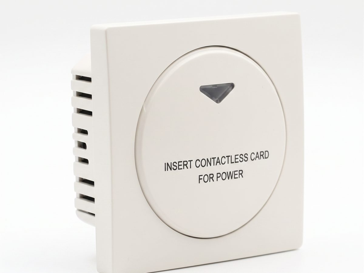
酒店取电开关 — 客房电源智能控制方案
酒店取电开关实现客房电源智能控制。RFID/IC卡识别,插卡取电,拔卡延时断电。220V交流,10A-16A,RS485或干接点。CE RoHS认证。OEM/ODM源头供应商。
当前页面已经把它作为下一步推荐内容直接指向。
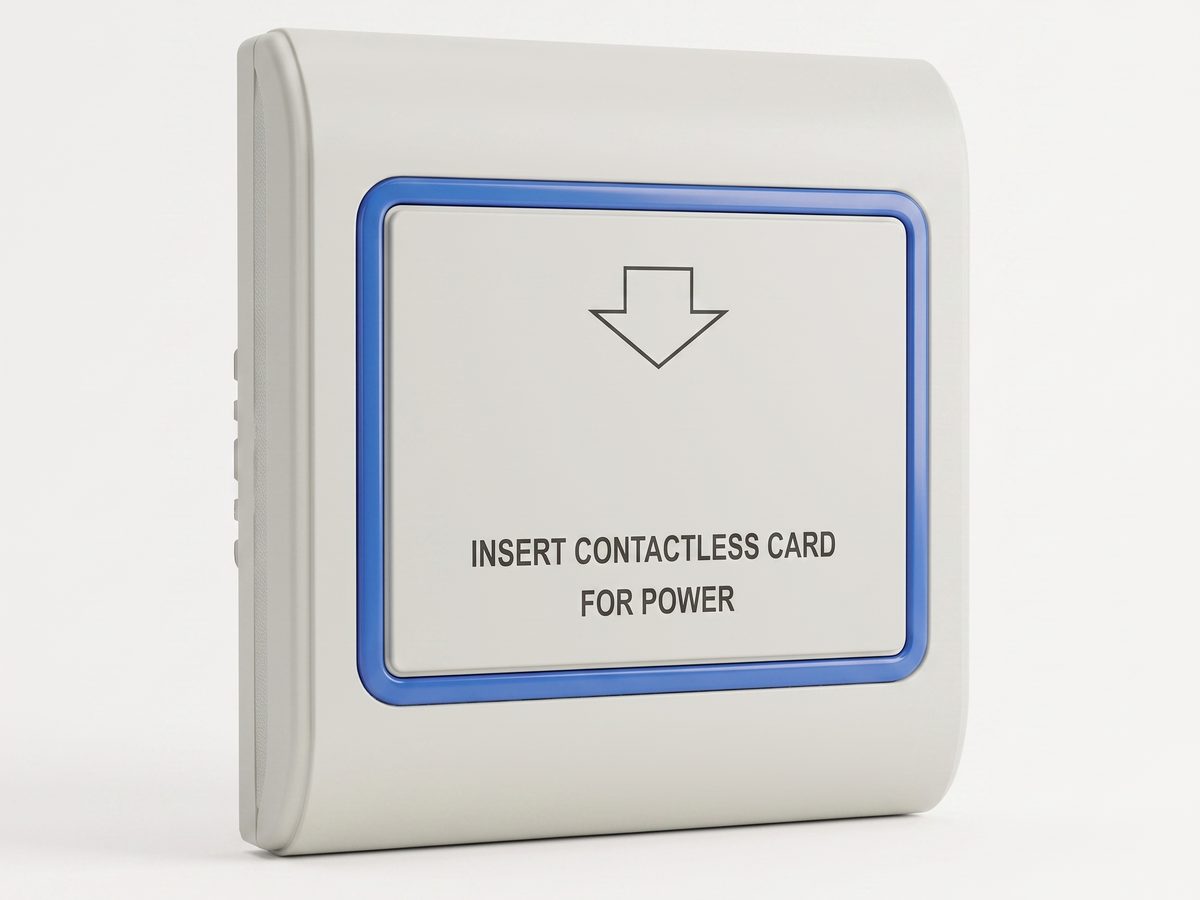
RFID 取电开关 — 13.56MHz 非接触式客房取电控制
RFID 取电开关采用 13.56MHz 非接触感应,客人轻触感应区即可取电,无需插卡槽。兼容酒店门锁系统,CE RoHS 认证,OEM/ODM 源头供应商。
当前页面已经把它作为下一步推荐内容直接指向。
相关解决方案
3相关文章
3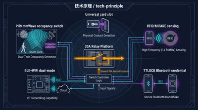
酒店取电开关五大控制模型详解:通用、RFID、TTLOCK、BLE 与占用传感器选型指南
酒店取电开关涵盖通用、RFID、TTLOCK、BLE 与占用传感器五大型号。本指南详解取电开关、插卡取电开关等核心词对应的产品家族,对比各模型读卡规则、组网方式与适用场景,助您按现有门锁系统精准选型,无需换卡即可实现客房节能 25-40%。
它服务于同一产品语境:酒店取电开关 — 客房电源智能控制方案。
RFID 与 NFC 酒店取电开关选型完全指南:125kHz 与 13.56MHz 卡技术核心差异
酒店取电开关选 RFID 还是 NFC?本质是卡技术家族与手机协议的区别:125kHz 与 13.56MHz RFID(MIFARE、Temic)是客房取电主流,支持扇区密钥绑定仅识自家房卡;NFC 只是手机模拟卡的贴近协议。文章对比读卡原理、防串用能力与选型建议,助工程商按现有门锁卡型精准决策。
它服务于同一产品语境:酒店取电开关 — 客房电源智能控制方案。
什么是酒店取电开关?核心工作原理、四大主流产品类型及客房节能 25-40% 的详细完整深度全解析
酒店取电开关插卡通电、取卡断电,客房节能 25-40%。对比通用型、RFID 型、TTLOCK 兼容型、BLE 智能型四大模式差异,涵盖 30A 继电器、15 秒延时、86 型底盒安装等关键参数,助您按现有刷卡系统精准选型,无需联网即可部署。
它服务于同一产品语境:酒店取电开关 — 客房电源智能控制方案。
与我们的工程师对接您的酒店项目
告知我们房间数量、吊顶类型、协议偏好,24 业务小时内返回打样方案和报价。
- 把泛化知识内容继续引向具体产品或应用场景讨论。
- 当客户要谈价格、图纸、MOQ 或项目节奏时,直接进入 RFQ。
- 同时保留直接联系入口,便于快速澄清问题和内部转交。