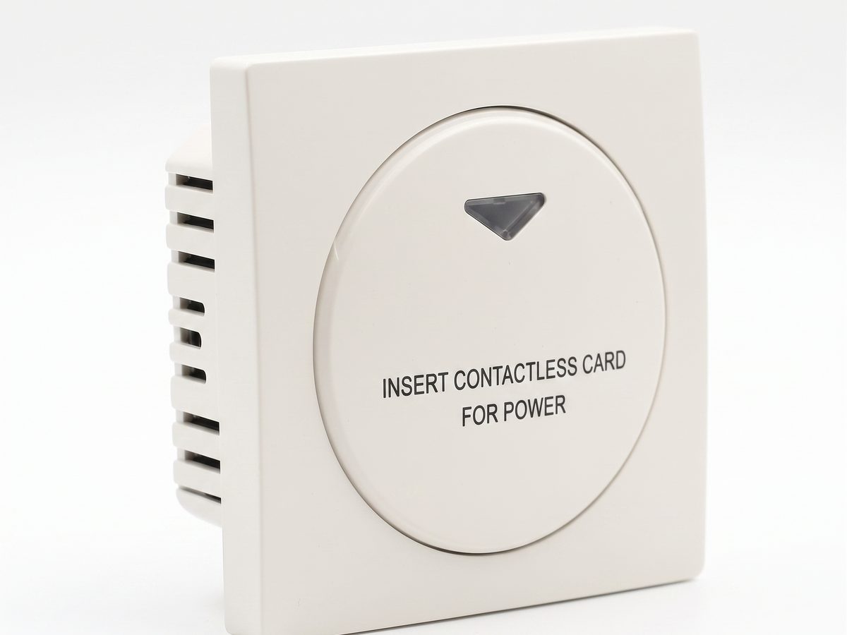
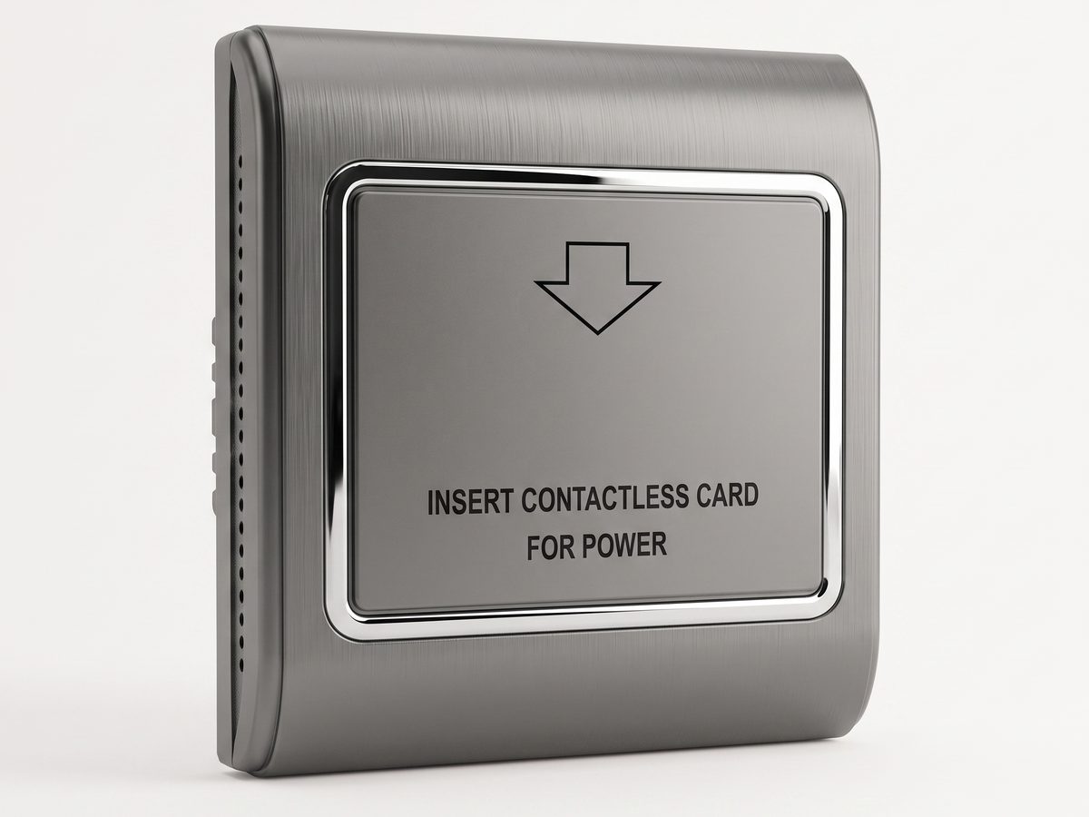
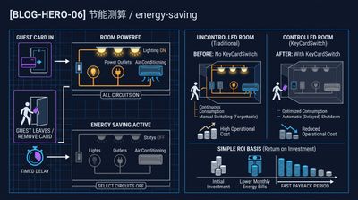
A wall-mounted card switch is designed to detect the guest card and provide a control signal. It is not automatically the correct device to carry every room load directly. A contactor allows the project to use a compact user interface while switching a circuit selected for its voltage, current, and electrical behavior.
This separation is useful for hotel rooms where air-conditioning, lighting, and outlets have different requirements. It also gives the electrical contractor a clear point at which to inspect, label, and service the controlled circuit. KeyCardSwitch Engineering Team helps buyers define the pairing; installation and final compliance remain the responsibility of the qualified site contractor.
Match components to the actual circuit
Start with the circuit schedule, not a nominal room count. Identify the supply voltage, normal operating current, starting or inrush current, load type, switching frequency, and whether the circuit is single-phase or otherwise configured. Air-conditioning equipment, fans, lighting drivers, and convenience outlets can each present different switching conditions.
The contactor should be selected with appropriate ratings and a suitable enclosure or mounting location. Confirm coil requirements, terminal access, conductor size, heat dissipation, and service clearance. The card switch must also fit the wall box and provide the required control output. A complete bill of materials should state which room circuits are controlled and which remain permanently supplied.
Make the guest sequence predictable
The operating sequence should be tested from the guest's perspective. Inserting the card should enable the intended room functions. Removing it should initiate the agreed shutdown behavior, including any delay that protects guest comfort or equipment. Re-inserting the card should restore operation consistently. Staff cards, service procedures, and maintenance isolation should be considered during acceptance testing.
Sample before volume purchase
A sample-room installation is the most efficient way to validate a switch-and-contactor arrangement. Use a representative room with the common wall box and typical loads. Ask the electrical contractor to verify terminations and protective devices. Then test normal operation, repeated card cycles, equipment restart, and behavior after a power interruption.
For properties with multiple room layouts, create a short configuration matrix instead of assuming one assembly fits every room. The matrix can list room type, card switch model, contactor model, controlled circuits, faceplate, and quantity. This gives procurement and installation teams the same reference.
A practical inquiry package
To request a recommendation, send the number of rooms, destination, supply voltage, maximum load current, load types, card technology, wall-box dimensions, and any available circuit diagram. Photos of the existing panel and switch are helpful. Tell us whether the project is a new installation, replacement, or phased retrofit.
KeyCardSwitch Engineering Team will review the information and return a proposed switch-and-contactor configuration, sample plan, and bill of materials. The purpose is not to overspecify hardware; it is to create a dependable room-power assembly that can be installed and maintained consistently. Contact the team when the load schedule is ready.