Guia de Instalação de Interruptor de Cartão de Hotel: Fiação Passo a Passo para Quartos de Hóspedes
Guia de instalação de interruptor de cartão de hotel para eletricistas e equipes de manutenção cobrindo preparação da caixa, fiação, conexão do relé, teste do cartão, temporização de desligamento atrasado e comissionamento.
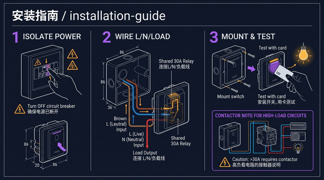
Um guia de instalação de interruptor de cartão de hotel é um método passo a passo para instalar um interruptor de energia controlado por cartão em um quarto de hóspedes, cobrindo preparação da caixa, isolamento elétrico, fiação da fase e carga no relé, montagem do painel embutido, teste de inserção do cartão e verificação do temporizador de desligamento atrasado. Um guia de instalação de interruptor de cartão de hotel é escrito para eletricistas, equipe de manutenção e integradores de sistemas que reformam quartos sem refazer a fiação principal, e trata o isolamento de segurança no ponto de distribuição como o primeiro passo. Um guia de instalação de interruptor de cartão de hotel conduz o instalador pela sequência: confirmar se a caixa acomoda o painel, conectar a alimentação do quarto nos contatos do relé, rotear um par de controle de baixa corrente para o painel, fixar o painel e confirmar que o relé fecha e o desligamento atrasado funciona antes que o circuito abra. Um guia de instalação de interruptor de cartão de hotel deixa claro que o trabalho é uma troca de painel mais uma conexão de relé, não uma refiação do quarto.
Preparando o Quarto para um Guia de Instalação de Interruptor de Cartão de Hotel
A fase de preparação de qualquer guia de instalação de interruptor de cartão de hotel começa com a confirmação da caixa de parede e do encaixe do painel. A unidade mais comum é um painel embutido de aproximadamente 86 mm por 86 mm, com um corpo traseiro de cerca de 48 mm de profundidade, dos quais aproximadamente 29 mm ficam dentro da parede quando montado. Antes de cortar qualquer coisa, o instalador deve medir a caixa unipolar existente — sua profundidade, suas orelhas de fixação e sua base — e compará-las às dimensões do corpo traseiro do interruptor. Um guia de instalação de interruptor de cartão de hotel trata o encaixe da caixa como uma verificação pré-instalação porque um painel que não assenta nivelado em uma caixa rasa não montará corretamente, e cortar uma caixa mais profunda em gesso acabado é muito mais disruptivo do que a própria fiação. Se a caixa for muito rasa ou danificada, o instalador deve instalar um extensor de caixa ou escolher uma variante de montagem em superfície antes de prosseguir.
O segundo passo de preparação em um guia de instalação de interruptor de cartão de hotel é reunir as ferramentas e materiais. O instalador precisa de um testador de tensão ou multímetro, chaves de fenda compatíveis com os parafusos de terminal e de fixação, uma lâmina plana pequena para os terminais, alicate de decapar, alicate de corte e o hardware de montagem do painel. Os materiais incluem condutores dimensionados adequadamente para os contatos do relé, um par de controle para o painel, prensa-cabos ou grommets onde o cabo entra na caixa e quaisquer placas adaptadoras necessárias para a caixa. Um guia de instalação de interruptor de cartão de hotel aconselha organizar tudo antes de começar para que o instalador não seja interrompido no meio da conexão, e alerta que toda conexão deve ser feita com o circuito isolado.
O terceiro passo de preparação é identificar o circuito do quarto e o caminho da carga. O instalador deve saber qual disjuntor ou fusível no ponto de distribuição alimenta este quarto, e deve rastrear como a fase de alimentação chega à posição do interruptor e como os condutores de carga seguem para as luzes, as tomadas e o termostato do ar-condicionado. Um guia de instalação de interruptor de cartão de hotel faz o instalador mapear a fiação existente em um esboço ou fotografia antes de tocar em qualquer coisa, porque a alimentação do quarto deve ser roteada através dos contatos do relé enquanto apenas um par de controle vai para o painel. O mal-entendido sobre qual cabo é a alimentação de entrada e qual é a carga de saída é a fonte mais comum de uma instalação que alimenta o painel, mas não comuta o quarto.
O quarto passo de preparação é confirmar a tensão e a polaridade da alimentação. O instalador deve verificar se a tensão medida na caixa corresponde à entrada nominal do interruptor, tipicamente 110 V ou 180–250 V CA, antes da conexão. Um guia de instalação de interruptor de cartão de hotel insiste em uma verificação de tensão viva com um medidor em vez de confiar no rótulo, porque uma alimentação mal identificada ou uma tensão parasita pode danificar o painel ou criar risco de choque. A polaridade do condutor de fase deve ser confirmada se os terminais da unidade forem marcados, porque conectar a fase no terminal errado é uma causa frequente de um painel que zumbida, não comuta ou eventualmente falha.
O quinto passo de preparação é decidir se um relé embutido ou um relé externo será usado. Se o interruptor tem um relé embutido, o instalador roteia a alimentação do quarto diretamente para os terminais de carga do painel. Se o modelo precisa de um relé externo ou contator porque a carga do quarto excede a capacidade interna, o instalador deve localizar um ponto de montagem para esse relé, próximo ao painel ou no quadro de distribuição, e passar um par de controle entre os dois. Um guia de instalação de interruptor de cartão de hotel trata essa decisão como parte da preparação para que o relé certo, o cabo certo e a posição de montagem certa estejam prontos antes que a energia seja isolada.
Isolamento de Segurança em um Guia de Instalação de Interruptor de Cartão de Hotel
A segurança é o primeiro mandamento de qualquer guia de instalação de interruptor de cartão de hotel, e começa com o isolamento do circuito do quarto no ponto de distribuição. Antes de qualquer tampa ser aberta, o instalador deve desligar o disjuntor ou retirar o fusível que alimenta o quarto e travar ou sinalizar o ponto de isolamento para que ninguém o reenergize durante o trabalho. Um guia de instalação de interruptor de cartão de hotel trata o bloqueio-sinalização como não negociável, porque um ajudante ou um eletricista que retorna e liga o disjuntor errado enquanto uma mão está na caixa pode causar um ferimento grave. O isolamento deve ser confirmado com um testador de tensão nos condutores na posição do interruptor, não assumido pela posição do disjuntor.
O segundo passo de segurança em um guia de instalação de interruptor de cartão de hotel é verificar tensão zero nos terminais exatos a serem trabalhados. Tensão pode estar presente mesmo com o disjuntor desligado se uma alimentação for compartilhada, se um circuito diferente passar pela caixa, ou se houver capacitância parasita no cabo. O instalador deve testar entre fase e neutro, entre fase e terra, e entre fase e fase na caixa e não encontrar tensão antes de conectar. Um guia de instalação de interruptor de cartão de hotel aconselha testar nos terminais, não apenas em um ponto remoto, porque um neutro compartilhado ou uma alimentação mal conectada em outro lugar pode deixar a caixa energizada.
O terceiro passo de segurança é trabalhar seco e limpo. Quartos de hóspedes são secos, mas o instalador ainda deve verificar infiltração de água, condensação ou vazamentos perto da caixa, e adiar o trabalho se houver umidade. A área de trabalho deve ser mantida livre de poeira e detritos para que nada caia na caixa aberta durante a conexão. Um guia de instalação de interruptor de cartão de hotel também observa que o instalador não deve trabalhar no circuito enquanto os aparelhos do quarto ou o ar-condicionado permanecerem energizados de forma que possa retroalimentar a fiação de controle, e deve garantir que todas as cargas conectadas estejam desligadas durante a fase de fiação.
O quarto passo de segurança é usar proteção pessoal e de componentes corretamente dimensionados. O instalador deve trabalhar com ferramentas isoladas, ficar em uma superfície não condutiva quando possível, e usar um testador de tensão fusível ou adequadamente dimensionado. Os condutores e terminais devem ser dimensionados para a corrente que conduzirão, e o painel e o relé devem ser dimensionados para a tensão de alimentação do quarto. Um guia de instalação de interruptor de cartão de hotel enfatiza que escolher componentes dimensionados acima da carga e tensão medidas, em vez de no limite exato, deixa uma margem de segurança que protege a instalação ao longo de anos de serviço.
A quinta consideração de segurança em um guia de instalação de interruptor de cartão de hotel é não introduzir novos pontos únicos de falha. O instalador deve evitar encadear cargas nos contatos do relé de forma que sobrecarregue uma conexão, deve apertar cada terminal no torque especificado, e deve re-verificar cada conexão após a carga do quarto ser aplicada. É mais seguro conectar cada circuito do quarto em seu próprio contato do relé onde a unidade fornece múltiplos canais do que agrupar vários circuitos em um terminal, porque um terminal solto ou sobrecarregado é uma fonte comum de calor e falha prematura.
Guia de Instalação de Interruptor de Cartão de Hotel: Conectando a Alimentação do Quarto ao Relé
O passo elétrico central em um guia de instalação de interruptor de cartão de hotel é conectar a alimentação do quarto nos contatos do relé. O instalador primeiro identifica a fase de entrada vinda do ponto de distribuição e a carga de saída que leva às luzes, tomadas e ar-condicionado do quarto. O contato comum do relé aceita a fase de entrada, e o contato normalmente aberto conecta ao lado da carga, de modo que quando o relé fecha, a energia flui da alimentação através dos contatos para o quarto. Um guia de instalação de interruptor de cartão de hotel faz o instalador confirmar a identificação dos contatos no relé — comum (C), normalmente aberto (NA) e normalmente fechado (NF) — e alerta que conectar no contato normalmente fechado por engano deixa o quarto energizado quando o cartão está ausente.
O condutor neutro é tratado de acordo com o design do interruptor. Em muitos interruptores de cartão, o leitor e a bobina do relé alimentam-se do lado da fase e o neutro passa direto para a carga inalterado, então o instalador conecta o neutro direto da alimentação para a carga do quarto. Alguns designs exigem um neutro no painel para a eletrônica. Um guia de instalação de interruptor de cartão de hotel diz que o tratamento correto do neutro está no diagrama de fiação, e o instalador deve segui-lo exatamente, porque deixar um neutro desconectado pode impedir o funcionamento do interruptor ou deixar o circuito inseguro em um design de neutro compartilhado.
O condutor de terra é conectado ao terminal de terra do painel e a quaisquer partes aterradas do corpo traseiro. Um guia de instalação de interruptor de cartão de hotel trata o aterramento como obrigatório onde a unidade fornece um terminal de terra, porque a placa traseira metálica e quaisquer partes condutoras expostas devem ser ligadas para proteger contra uma falha. A terra deve ser conectada firmemente e deve ser contínua até a distribuição aterrada do quarto. Onde a caixa existente não tem terra, o instalador deve sinalizar a deficiência em vez de conectar o painel sem terra, porque uma falha em um painel sem terra pode energizar as partes metálicas.
O par de controle entre o interruptor e qualquer relé externo é então roteado. Se a unidade aciona um relé externo, o instalador passa um par de baixa corrente da saída de controle do painel para os terminais da bobina do relé. Este par conduz apenas a corrente de acionamento da bobina, alguns miliampères a algumas centenas de miliampères, então pode ser de bitola menor que a alimentação do quarto, mas deve ser protegido e roteado longe de bordas danificadas ou afiadas. Um guia de instalação de interruptor de cartão de hotel faz o instalador rotular o par de controle
A hotel key card switch installation guide is a step-by-step method for fitting a card-controlled power switch into a guest room, covering box preparation, electrical isolation, wiring the line and load to the relay, mounting the flush panel, testing card insertion, and verifying the delay-off timer. A hotel key card switch installation guide is written for electricians, maintenance staff, and system integrators who retrofit rooms without major rewiring, and it treats safety isolation at the distribution point as the first step. A hotel key card switch installation guide leads the installer through the sequence: confirming the box fits the panel, landing the room feed on the relay contacts, routing a low-current control pair to the plate, securing the panel, and confirming the relay closes and the delay-off works before the circuit opens. A hotel key card switch installation guide makes clear the job is a panel swap plus a relay connection, not a rewire of the room.
Preparing the Room for a Hotel Key Card Switch Installation Guide
The preparation phase of any hotel key card switch installation guide begins with confirming the wall box and the panel fit. The most common unit is a flush panel of roughly 86mm by 86mm, with a back body about 48mm deep, of which roughly 29mm sits inside the wall when mounted. Before cutting anything, the installer should measure the existing single-gang box — its depth, its screw ears, and its footprint — and compare them to the switch's back-body dimensions. A hotel key card switch installation guide treats box fit as a pre-install verification because a panel that does not sit flush in a shallow box will not mount cleanly, and cutting a deeper box in finished plaster is far more disruptive than the wiring itself. If the box is too shallow or damaged, the installer must either fit a box extender or choose a surface-mount variant before proceeding.
The second preparation step in a hotel key card switch installation guide is gathering the tools and materials. The installer needs a voltage tester or multimeter, screwdrivers matching the terminal and fixing screws, a small flat blade for the terminals, wire strippers, cable cutters, and the panel's mounting hardware. The materials include properly sized conductors for the relay contacts, a control pair to the panel, cable glands or grommets where the cable enters the box, and any adapter plates needed for the box. A hotel key card switch installation guide advises laying these out before starting so the installer is not interrupted mid-connection, and cautions that every connection must be made with the circuit isolated.
The third preparation step is identifying the room circuit and the load path. The installer must know which breaker or fuse at the distribution point feeds this room, and must trace how the live feed reaches the switch position and how the load leads onward to the lights, the sockets, and the air-conditioning thermostat. A hotel key card switch installation guide has the installer map the existing wiring on a sketch or photograph before touching anything, because the room feed must be routed through the relay contacts while only a control pair goes to the panel. Misunderstanding which cable is the incoming feed and which is the outgoing load is the most common source of an installation that powers the panel but does not switch the room.
The fourth preparation step is confirming the supply voltage and polarity. The installer should verify the measured voltage at the box matches the switch's rated input, typically 110V or 180–250V AC, before connection. A hotel key card switch installation guide insists on a live-voltage check with a meter rather than trusting the label, because a misidentified feed or a stray voltage can damage the panel or create a shock hazard. The live conductor polarity should be confirmed if the unit's terminals are marked, because landing the line on the wrong terminal is a frequent cause of a panel that hums, fails to switch, or eventually fails.
The fifth preparation step is deciding whether a built-in relay or an external relay will be used. If the switch has a built-in relay, the installer routes the room feed directly to the panel's load terminals. If the model needs an external relay or contactor because the room load exceeds the internal rating, the installer must locate a mounting point for that relay, close to the panel or at the distribution board, and run a control pair between the two. A hotel key card switch installation guide treats this decision as part of preparation so that the right relay, the right cable, and the right mounting position are ready before the power is isolated.
Safety Isolation in a Hotel Key Card Switch Installation Guide
Safety is the first commandment of any hotel key card switch installation guide, and it starts with isolating the room circuit at the distribution point. Before any cover is opened, the installer must switch off the circuit breaker or withdraw the fuse feeding the room and lock or tag the isolation point so no one re-energizes it during work. A hotel key card switch installation guide treats lockout-tagout as non-negotiable, because a helper or a returning electrician who flips the wrong breaker while a hand is in the box can cause a serious injury. The isolation must be confirmed with a voltage tester on the conductors at the switch position, not assumed from the breaker position.
The second safety step in a hotel key card switch installation guide is verifying zero voltage at the exact terminals to be worked. Voltage can be present even with the breaker off if a feed is shared, if a different circuit wanders through the box, or if there is a stray capacitance in the cable. The installer should test between live and neutral, between live and earth, and between live and live at the box and find no voltage before connecting. A hotel key card switch installation guide advises testing at the terminals, not just at a remote point, because a shared neutral or miswired feed elsewhere can leave the box live.
The third safety step is working dry and clean. Guest rooms are dry, but the installer should still check for water ingress, condensation, or leaks near the box, and postpone the work if moisture is present. The work area should be kept free of dust and debris so nothing falls into the open box during connection. A hotel key card switch installation guide also notes that the installer should not work on the circuit while the room's appliances or the air-conditioning remain energized in a way that could back-feed the control wiring, and should ensure all connected loads are off during the wiring phase.
The fourth safety step is using correctly rated personal and component protection. The installer should work with insulated tools, stand on a non-conductive surface where possible, and use a fused or appropriately rated voltage tester. The conductors and terminals must be rated for the current they will carry, and the panel and relay must be rated for the room's supply voltage. A hotel key card switch installation guide emphasizes that choosing components rated above the measured load and supply, rather than at the exact rating, leaves a safety margin that protects the installation over years of service.
The fifth safety consideration in a hotel key card switch installation guide is not introducing new single-point failures. The installer should avoid daisy-chaining loads on the relay contacts in a way that overloads one connection, should tighten every terminal to its specified torque, and should re-check each connection after the room's load is applied. It is safer to land each room circuit on its own relay contact where the unit provides multiple channels than to crowd several circuits onto one terminal, because a loose or overloaded single terminal is a common source of heat and premature failure.
Hotel Key Card Switch Installation Guide: Wiring the Room Feed to the Relay
The core electrical step in a hotel key card switch installation guide is landing the room feed on the relay contacts. The installer first identifies the incoming live feed from the distribution point and the outgoing load that leads to the room's lights, sockets, and air-conditioning. The relay's common contact accepts the incoming live, and the normally-open contact connects to the load side, so that when the relay closes, power flows from the feed through the contacts to the room. A hotel key card switch installation guide has the installer confirm the contact identification on the relay — common (C), normally open (NO), and normally closed (NC) — and warns that wiring into the normally-closed contact by mistake leaves the room powered when the card is absent.
The neutral conductor is handled according to the switch's design. On many key card switches, the reader and relay coil draw from the line side and the neutral is passed through to the load unchanged, so the installer connects the neutral straight through from the supply to the room load. A few designs require a neutral at the panel for the electronics. A hotel key card switch installation guide says the correct neutral treatment is stated on the wiring diagram, and the installer should follow it exactly, because leaving a neutral unconnected can prevent the switch from operating or leave the circuit unsafe on a shared-neutral design.
The earth conductor is connected to the panel's earth terminal and to any earthed parts of the back body. A hotel key card switch installation guide treats earthing as mandatory where the unit provides an earth terminal, because the metal back plate and any exposed conductive parts must be bonded to protect against a fault. The earth should be landed securely and should be continuous to the room's earthed distribution. Where the existing box has no earth, the installer should flag the deficiency rather than connect the panel un-ear, because a fault on an un-ear panel can energize the metalwork.
The control pair between the switch and any external relay is then routed. If the unit drives an external relay, the installer runs a low-current pair from the panel's control output to the relay coil terminals. This pair carries only the coil drive current, a few milliamps to a few hundred milliamps, so it can be smaller-gauge than the room feed, but it must be protected and routed away from damaged or sharp edges. A hotel key card switch installation guide has the installer label the control pair clearly so a future technician does not mistake it for a load conductor and chase a phantom fault.
Once all conductors are landed, the installer tightens every terminal to its specified torque and double-checks that no strand of a multi-strand conductor is loose or pinched against an adjacent terminal. A hotel key card switch installation guide emphasizes this re-check because a loose conductor is invisible to a visual glance and is a leading cause of intermittent contact, heat, and eventual failure. After tightening, the installer should gently tug each conductor to confirm it is held firmly before mounting the panel, because reconnecting after the panel is in place is far more awkward.
Hotel Key Card Switch Installation Guide: Connecting the Switch Panel and Control Circuit
With the feed and load landed, a hotel key card switch installation guide moves to connecting the panel's control terminals. The panel has a small set of terminals: the input side or the reader supply, the relay drive output, and any terminals for the delay or override section. The installer connects the panel's line supply to the live feed, connects its neutral and earth per the diagram, and lands the relay control output on the relay coil or the panel's own integrated relay input. A hotel key card switch installation guide advises organizing the conductors in the box so the panel slides in without pinching, and leaving enough slack that the panel can be withdrawn later for service without straining the terminals.
The panel's integrated relay, where fitted, receives the room feed directly on its load terminals. In that case the installer lands the incoming live on the relay common and the outgoing room load on the normally-open contact, both within the back body. A hotel key card switch installation guide notes that an integrated-relay unit makes the connection self-contained and removes the need for a remote relay, but it also means the relay is inside the flush box, so the box must have room for the relay plus the wiring without overcrowding. If the box is tight, the installer should re-route the conductors to avoid sharp bends against the relay body.
The delay and override settings are set during this phase for models that allow adjustment. Where the unit has a jumper, a small rotary switch, or a dip switch for the delay-off value, the installer sets it to the value chosen by the property, commonly 15 seconds. Where a manual override for housekeeping exists, the installer confirms it is in the correct starting position, normally card-controlled rather than permanently on. A hotel key card switch installation guide has the installer set these controls now, with the diagram in hand, because adjusting them after the face is mounted is awkward and easily forgotten, leaving the room with an unintended delay or a permanently energized circuit.
The reader connection is confirmed before final mounting. The card reader head, whether a magnetic slot or an RFID read zone, connects to the panel's controller either through a fixed ribbon or a pluggable connector. The installer should seat the connector fully and verify it latches, because a partially seated reader connector is a classic intermittent fault that makes the switch work only intermittently. A hotel key card switch installation guide advises confirming the reader is detected by observing the panel's indicator behavior during the test, since most units light a lamp when the reader and controller are communicating.
The wiring entries are sealed before the panel is secured. Any knockout or entry not used should be closed so dust and insects cannot enter the box, and gland or grommet should protect the cable where it passes through the back body. A hotel key card switch installation guide treats this sealing as a small but real reliability step, because a sealed box keeps the electronics clean, prevents moisture intrusion, and avoids the service calls that a compromised box invites over time.
Hotel Key Card Switch Installation Guide: Mounting the Flush Panel and Securing the Back Body
Mounting begins, in a hotel key card switch installation guide, with fitting the back body into the wall box. The back body slides into the single-gang box, with its wiring routed through the entries and its screw holes aligned to the box's ears. The installer lowers the body in, making sure the conductors are not trapped between the body and the box wall, and that the flex of the cable does not pull a terminal loose. A hotel key card switch installation guide has the installer seat the body fully so its mounting flange sits flush against the wall surface, which is the point at which the panel's 29mm embedment fills the box depth cleanly.
The back body is then secured. Most units fix to the box ears with two mounting screws, and some also fix to a frame or directly to the wall. The installer tightens the screws evenly, alternating between the two or four fixing points, so the body seats square and does not tilt. A hotel key card switch installation guide warns against over-tightening, which can crack a plastic back body or strip the mount, and against under-tightening, which leaves the panel loose and wobbly. The goal is a firm, level seat with the flange held flat against the wall on all sides.
The face plate is then clipped or screwed over the back body. The face locks over the flange, covering the screws and the box, and carries the card slot or the RFID read zone and any indicator lamp. The installer aligns the face so the card slot lines up with the reader and so the plate is level with the wall, then locks it in place. A hotel key card switch installation guide notes that the face should engage cleanly with a click or a seated screw, and that a face that will not seat again after removal usually signals a trapped conductor or a slightly misaligned back body that must be corrected before the room is finished.
After the face is on, the installer checks the alignment and clearance of the card slot. The card should slide into a magnetic slot with light, even resistance, and the RFID read zone should be accessible on the face without obstruction. A hotel key card switch installation guide has the installer insert and withdraw a card several times immediately after mounting to confirm the slot is not blocked and the reader operates through the face, because a subtle misalignment is far easier to fix before the face is sealed and the room is handed over.
Finally at the mounting stage, the installer verifies the panel is level and that the face does not protrude or rock. The finished panel should sit flat and stable, with no movement when a card is inserted or the indicator is pressed. A hotel key card switch installation guide treats a stable, level, flush-mount finish as part of the deliverable, because a crooked or loose panel reads as a poor installation even when electrically it works perfectly, and it invites the guest to tamper with a device that does not look well-fitted.
Hotel Key Card Switch Installation Guide: Connecting and Mounting an External Relay or Contactor
For rooms whose load exceeds the switch's internal relay rating, a hotel key card switch installation guide covers external relay connection in detail. The external relay or contactor is mounted at a suitable point, either on a DIN rail at the distribution board or on a backplate near the switch. The room feed is routed through the contactor's main contacts, and the switch's low-current control pair connects to the contactor coil. A hotel key card switch installation guide has the installer confirm the contactor's coil voltage matches the switch's control output, because a mismatch means the coil never pulls in and the room never powers.
The contactor's main contact wiring follows the same common-and-normally-open logic as the internal relay. The incoming live lands on the contactor's line side, the outgoing room load lands on the load side, and when the coil is energized the contacts close to complete the room circuit. A hotel key card switch installation guide confirms the contactor is selected so its main contact rating exceeds the measured room load with margin, and that its coil accepts the switch's control signal, whether that is the line voltage or a low-voltage DC output depending on the model.
The control wiring from the switch to the contactor coil is the piece most sensitive to wrong connection. The installer routes a clearly labeled pair from the panel's control output to the contactor's coil terminals, observing polarity if the coil is DC or if the unit marks it. A hotel key card switch installation guide has the installer avoid running the control pair alongside high-current cables where possible, or use a screened pair if they must run together, to prevent induced noise from toggling the coil. The control circuit should be fused or protected per the diagram, because a short on the control pair could otherwise feed a fault into the panel.
The contactor should be mounted to dissipate its heat. A current-carrying contactor produces some heat in its coil and contacts, so it needs clearance and ventilation rather than being buried tightly in an enclosed space. A hotel key card switch installation guide advises mounting the contactor with a little airspace, securing it firmly so it cannot vibrate or rock, and leaving its terminals accessible for service. A heat-soaked or loose contactor shortens coil and contact life and is harder to service when it eventually needs attention.
Finally, the installer labels the external relay clearly. A note on or beside the contactor stating it is the key card relay for a specific room number lets maintenance find it quickly and avoids someone re-wiring it by mistake during later work. A hotel key card switch installation guide treats labeling as a standard part of professional installation, because an unlabeled relay at a distribution board is a costly guess for the next technician, and a labeled one turns a diagnostic into a two-minute job.
Hotel Key Card Switch Installation Guide: Testing Card Insertion and Relay Operation
Testing is the point where a hotel key card switch installation guide confirms the wiring actually works, and it should always be done on a dummy lamp before the room is handed over. The installer connects a simple test lamp or a small resistive load on the switched circuit, isolates the room's real load, and starts the test with the circuit still controlled from a safe point. A hotel key card switch installation guide insists on the dummy load on first test because it prevents a wiring error from energizing the room's real circuits unexpectedly, and because it isolates the switch's behavior from any load fault.
The first test is the card-insertion test. With a valid card of the correct medium inserted into the slot or held against the reader, the panel's indicator should change and the relay should close within about one second, energizing the test lamp. If the lamp does not light, the installer checks the card medium, the reader connection, the relay wiring, and the panel supply in that order. A hotel key card switch installation guide advises troubleshooting stepwise: card recognized, read signal reaches the controller, controller drives the relay, contacts close, load conducts, and building each step's confirmation before moving to the next.
The second test is the delay-off test. With the card removed, the relay should stay closed for the set delay, typically 15 seconds, then open and cut the test lamp. The installer times this with a stopwatch or the panel's own indicator and confirms the delay matches the configured value. A hotel key card switch installation guide has the installer repeat this test a few times, and also reinsert the card during the delay window to confirm the switch re-energizes without toggling, because a switch that erroneously toggles on a reinsertion is confusing and should be corrected before handover.
The third test is the override check, where the unit has a manual override for housekeeping. The installer engages the override and confirms the test lamp energizes without a card, then resets the override and confirms the switch returns to card-controlled operation and the lamp cuts on delay after card removal. A hotel key card switch installation guide treats a functioning override as a requirement only if the property uses it for cleaning, but it should be verified either way so its behavior is known.
The fourth test is a repeat-operation and stability check. The installer inserts and removes the card perhaps twenty times and confirms the relay opens and closes reliably on every cycle without sticking or chattering, and that the panel does not overheat. A hotel key card switch installation guide advises this endurance pass on a sample before committing the whole property, because the failures it reveals — a loose terminal, an intermittent reader seat, a marginal relay — are exactly the ones that would otherwise surface in a live guest room.
Hotel Key Card Switch Installation Guide: Verifying the Delay-Off Timer and Adjusting the Setting
Setting and verifying the delay-off timer is its own step in a hotel key card switch installation guide. Most units select the delay with a jumper, a small rotary switch, a dip switch, or an on-board potentiometer, and the installer sets it to the value the property chose, commonly 15 seconds. The setting should be made with the unit documented, because the selector position is easy to misread against a small print legend. A hotel key card switch installation guide has the installer set the delay as part of the wiring phase, then verify it in the test phase so the two are not separated by a forgotten adjustment.
The delay behaves as a fixed interval from the moment the card is removed. The installer should confirm the timer starts on card removal rather than on any other event, and that all the switched circuits drop together when the timer elapses. A hotel key card switch installation guide notes that some two-channel units time the lighting and the air-conditioning channels differently, letting the lighting drop after a short delay while a controlled device shuts down more slowly, and the installer should verify each channel's delay against the expected configuration.
If the property has multiple room types or different housekeeping habits, the delay may need to differ by room. A hotel key card switch installation guide advises recording the chosen delay per room type on the installation record so the settings are traceable, and testing one sample of each room type rather than assuming one setting fits all. A uniform default covers most rooms, but a slow-shutting air-conditioning controller in one wing might justify a longer delay for that wing, and documenting it prevents later confusion.
The installer should also confirm the delay is stable over repeated cycles. A timer that drifts, that triggers early, or that sometimes fails to open the circuit entirely is a fault, not a tolerance, and the installer should replace or repair the unit rather than accept it. A hotel key card switch installation guide treats a reliable, repeatable timer as a quality bar, because an energy-saving switch that randomly leaves the room powered undermines the entire purpose of the installation.
The delay verification concludes by re-inserting a card during the countdown and confirming the relay stays latched on a repeated cycle. This unit-of-behavior check confirms the switch reads a reinserted card as a continuation, not a new event. A hotel key card switch installation guide closes this step by confirming the final delay value is set to the property's requirement, is recorded on the as-built sheet, and is consistent across all the rooms installed in the same campaign.
Hotel Key Card Switch Installation Guide: Commissioning the Room and Completing the Handover
Commissioning is the final phase of a hotel key card switch installation guide, where the room's real load is reconnected and the installation is confirmed working under genuine conditions. The installer re-energizes the room's real circuits, connects the actual lights, sockets, and air-conditioning to the switched feed, and runs the card-insert test once more with the real load rather than the dummy lamp. A hotel key card switch installation guide has the installer confirm the relay carries the real room load without overheating or buzzing, and that every circuit the switch controls actually powers up.
The second commissioning check is a full functional pass of every switched feature. The installer confirms each light, each socket, and the air-conditioning respond correctly to the card: all live with the card inserted, all cut together after the delay on card removal. A hotel key card switch installation guide has the installer involve a second pair of eyes or a checklist so no circuit is missed, because a retrofit that leaves one socket permanently unswitched or one light uncontrolled is a defect that surfaces only when a guest complains.
The third check is tidiness and safety at the box. The installer confirms all conductors are secured, terminals tight, unused entries sealed, and the panel and any external relay fixed firmly. A hotel key card switch installation guide treats the finished box as a deliverable: neat, no bare cable, no crowding, and a panel that sits flush and level. This final inspection catches loose work that could pass a functional test but cause a fault or a nuisance later.
The fourth check is restoring the room to service and handing it over. The installer ensures the room is left with the card switch in its normal card-controlled state, the front desk is advised that the unit is live, and the room is clean and correctly finished before it is released. A hotel key card switch installation guide notes that housekeeping staff should be told the basic behavior — insert the card to power, remove it to cut after the delay — so they do not mistake the intentional delay-off for a fault, and so they use the override correctly if one is fitted.
Finally, the installer records the completed installation. The as-built record should note the room number, the model, the card medium, the delay set, the override behavior, and any settings deviating from the default. A hotel key card switch installation guide advises keeping these records per room for the whole property, because they make later service, spares ordering, and troubleshooting dramatically faster. A complete, accurate record turns a retrofit from a one-off installation into a manageable part of the property's ongoing electrical maintenance.
Hotel Key Card Switch Installation Guide: Retrofitting Without Downtime
A hotel key card switch installation guide is most valuable to a working hotel when the owner can retrofit without taking rooms out of service for long. The practical approach is to batch the work by floor and schedule each room during its natural vacancy, not to shut down an entire wing at once. Each room typically needs less than an hour of active work once the electrician is practiced, so a two-person team can move through a floor efficiently while the sales office marries the work to occupancy. The guide has the installer confirm the room arrangement before starting, remove only the face plate and switch being replaced, and keep the guest room furniture and finishes protected during the swap. For phased projects, the owner standardizes on one card medium and one delay setting across every wing so the behavior is uniform for guests and for housekeeping. A hotel key card switch installation guide that plans for phasing, protects finishes, and standardizes configuration turns a large retrofit into a sequence of short, predictable room visits rather than a disruptive project, which is why phased delivery is now the default for occupied properties.
Part of this article content is generated by AI and optimized for professional accuracy and readability.
Não sabe qual sensor se adapta ao seu projeto?
Fale com nossos engenheiros de aplicação mmWave para uma consulta gratuita.
Encontre o sensor de presença certo para o seu projeto hoteleiro
Compare os 3 protocolos, veja casos hoteleiros e baixe o guia de instalação
Produtos relacionados
3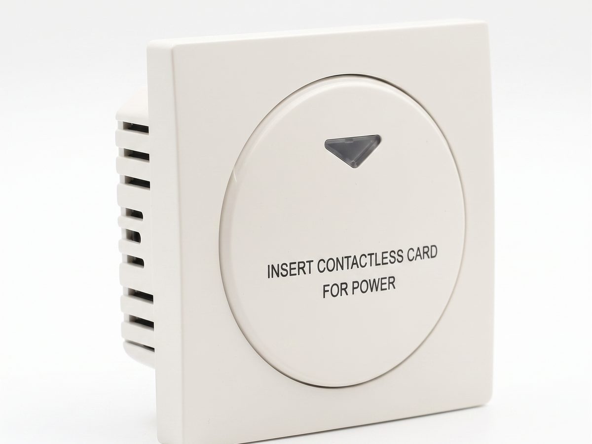
Interruptor de Cartão de Hotel — Controle de Energia do Quarto
Interruptor de cartão de hotel para controle de energia do quarto. Detecção RFID/IC, insira e ligue, desligamento temporizado ao remover. 220V CA, 10A-16A, RS485 ou contato seco. CE RoHS. Fornecedor OEM/ODM.
Esta página já o indica como a próxima referência recomendada.
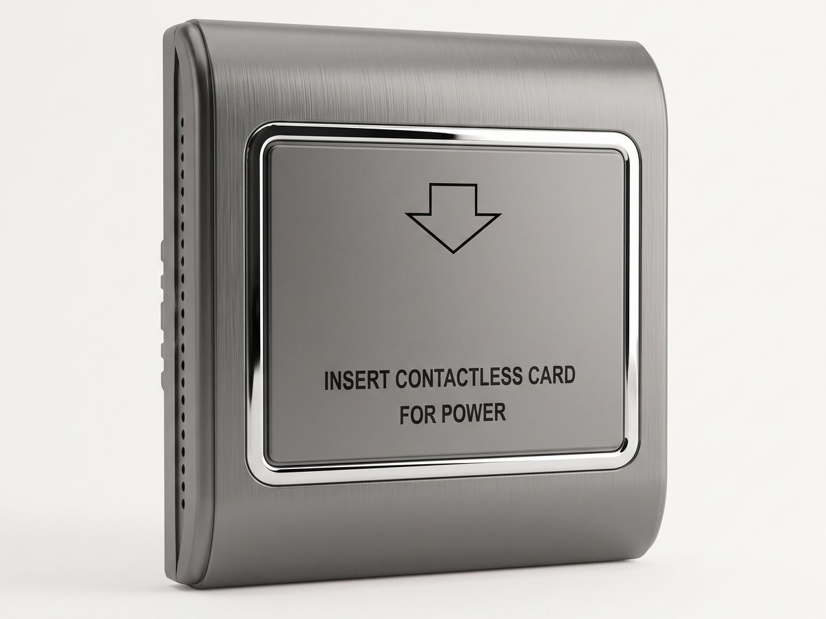
Interruptor RFID de Economia de Energia — Interruptor de Cartão MIFARE Vinculado ao Quarto (Tipo B)
Interruptor RFID de economia de energia que vincula a energia a um cartão MIFARE específico do quarto. MIFARE 13,56MHz / Temic 125kHz, CA 180–250V, 30A, desligamento atrasado 15s. Um interruptor RFID de hotel que impede o compartilhamento de cartões entre quartos e reduz 25–40% da energia do quarto.
Esta página já o indica como a próxima referência recomendada.
Interruptor de Energia Compatível TTLOCK — Vinculado ao Quarto + Tempo Limitado (Tipo C)
Interruptor de energia compatível TTLOCK com ID do quarto e limite de tempo. Funciona com cartões MIFARE TTLOCK/TTHotel via autenticação de chave de setor, CA 180–250V, 30A. Um interruptor de cartão criptografado e interruptor de energia TTLOCK ES2 para retrofits de hotéis com ecossistema fechado.
Esta página já o indica como a próxima referência recomendada.
Soluções relacionadas
3 Guia de Compra de Interruptores de Economia de Energia para Hotéis 2026
Guia de compra de interruptores de economia de energia para hotéis abrangendo cartão universal, RFID/MIFARE, compatível com TTLOCK, BLE inteligente e interruptores de sensor de ocupação. Escolha o interruptor de energia por cartão-chave, interruptor de energia por inserção de cartão e interruptor de economia de energia por chave ideal para seus quartos.
Esta página já o indica como a próxima referência recomendada.
Sistema de Gestão de Energia Hoteleira — Controle de Energia do Quarto com Retorno
Um sistema de gestão de energia hoteleira baseado em interruptores de cartão-chave, economizadores RFID e sensores de ocupação que reduz 25–40% da eletricidade dos quartos. Guia de controlador de energia para hotéis que modernizam a energia dos quartos.
Esta página já o indica como a próxima referência recomendada.
Sistema de Gestão de Quartos Baseado em Controle de Energia por Cartão
Um sistema prático de gestão de quartos de hóspedes para controle de energia através de interruptores de cartão, contatores e regras operacionais claramente documentadas.
Suporta o mesmo contexto de produto: Interruptor de Cartão de Hotel — Controle de Energia do Quarto, Interruptor RFID de Economia de Energia — Interruptor de Cartão MIFARE Vinculado ao Quarto (Tipo B).
Artigos do blog relacionados
3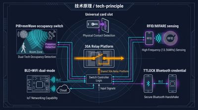
Interruptor de Cartão de Hotel: Tipos, Modelos e Como Especificar
O interruptor de cartão de hotel abrange modelos universal, RFID, TTLOCK, BLE e de ocupação. Guia completo sobre a família key card/keycard cobrindo termos principais.
Suporta o mesmo contexto de produto: Interruptor de Cartão de Hotel — Controle de Energia do Quarto, Interruptor RFID de Economia de Energia — Interruptor de Cartão MIFARE Vinculado ao Quarto (Tipo B), Interruptor de Energia Compatível TTLOCK — Vinculado ao Quarto + Tempo Limitado (Tipo C).

RFID vs NFC em Interruptores de Cartão-Chave: Qual Escolher
RFID vs NFC em interruptores de cartão-chave: RFID 125kHz/13,56MHz (MIFARE, Temic) é o padrão para energia no quarto; NFC é o protocolo do telemóvel. Compare alcance, fidelização e compatibilidade.
Suporta o mesmo contexto de produto: Interruptor RFID de Economia de Energia — Interruptor de Cartão MIFARE Vinculado ao Quarto (Tipo B), Interruptor de Cartão de Hotel — Controle de Energia do Quarto, Interruptor de Energia Compatível TTLOCK — Vinculado ao Quarto + Tempo Limitado (Tipo C).
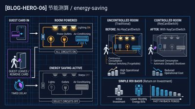
O Que É um Interruptor de Cartão-Chave de Hotel e Como Poupa
Um interruptor de cartão-chave de hotel alimenta o quarto quando o cartão é inserido e corta a energia quando removido, economizando tipicamente 25–40% da eletricidade do quarto.
Suporta o mesmo contexto de produto: Interruptor de Cartão de Hotel — Controle de Energia do Quarto, Interruptor RFID de Economia de Energia — Interruptor de Cartão MIFARE Vinculado ao Quarto (Tipo B), Interruptor de Energia Compatível TTLOCK — Vinculado ao Quarto + Tempo Limitado (Tipo C).
Especifique o seu projeto hoteleiro com os nossos engenheiros
Envie a contagem de quartos, tipo de teto e preferência de protocolo. Retornaremos um plano de amostras e orçamento em 24 horas úteis.
- Passe da orientação geral para uma discussão de produto ou aplicação.
- Use RFQ quando preço, desenhos, MOQ ou calendário de lançamento precisam de estrutura.
- Mantenha um caminho de contacto direto visível para esclarecimentos rápidos e passagem de testemunho.