Integrasi HVAC Sakelar Kartu Kunci Hotel: Kontrol Daya AC
Panduan integrasi HVAC sakelar kartu kunci hotel mencakup kontrol daya AC, pengkabelan termostat, delay-off kompresor, dan pengalihan kontaktor beban tinggi.
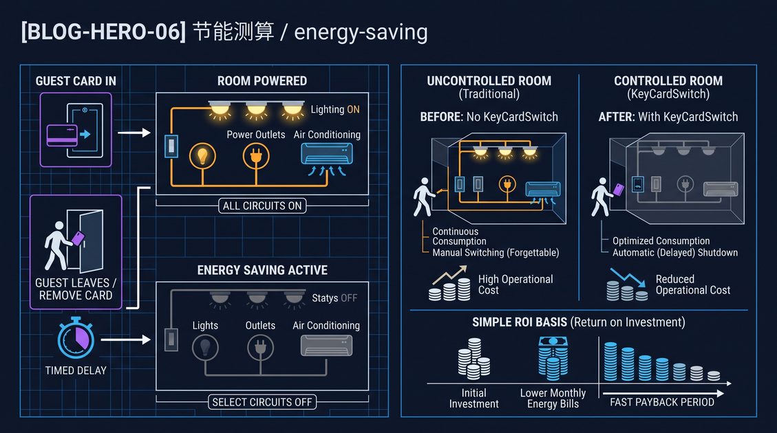
Integrasi HVAC sakelar kartu kunci hotel adalah praktik menghubungkan sakelar daya berbasis kartu di kamar ke sirkuit pendingin dan pemanas ruangan sehingga HVAC hanya menyala selama kartu tamu yang valid dimasukkan. Dalam integrasi HVAC sakelar kartu kunci hotel yang umum, sakelar membaca kartu di pintu masuk dan menutup sirkuit kontrol yang memberi daya pada unit HVAC dalam ruangan bersama lampu dan soket, lalu membuka sirkuit tersebut setelah jeda singkat saat kartu ditarik. Tujuannya adalah penghematan energi dengan tidak menjalankan kompresor dan kipas di kamar kosong, sementara termostat dinding dalam ruangan tetap mengatur setpoint dan kecepatan kipas di dalam ruangan berpendingin. Karena pendingin udara biasanya merupakan beban listrik terbesar di kamar tamu, cara sakelar kartu terhubung ke saluran daya AC menentukan seberapa besar beban yang harus dialihkan sakelar dan seberapa aman kompresor dimatikan.
Apa yang Sebenarnya Dikontrol oleh Integrasi HVAC Sakelar Kartu Kunci Hotel
Integrasi HVAC sakelar kartu kunci hotel mengontrol sisi daya dari paket penataan suhu kamar, bukan setpoint suhu. Saat kartu valid dimasukkan, sakelar kartu kunci menutup relai atau kontaktornya dan menyalakan sirkuit cabang yang memberi daya pada unit dalam ruangan, termostat dinding, dan biasanya juga pencahayaan serta soket umum; saat kartu ditarik, sakelar yang sama memutus sirkuit tersebut sehingga kompresor HVAC, kipas sirkulasi, dan elektronika standby berhenti menarik daya. Termostat dinding dalam ruangan terus membaca suhu kamar dan memberi perintah pemanasan atau pendinginan, tetapi hanya selama sirkuit berpendingin aktif. Ini adalah desain pemutus daya, berbeda dari desain kontrol pintar yang berkomunikasi dengan AC melalui bus data. Integrasi HVAC sakelar kartu kunci hotel yang dasar karenanya melindungi properti dari kamar kosong yang menjalankan kompresor berjam-jam, dan ini adalah retrofit paling sederhana karena hanya menambahkan interlock kontrol pada saluran cabang AC yang ada tanpa mengganti termostat atau memasang jaringan controller.
Pemisahan antara Kontrol Daya dan Kontrol Suhu
Cara termudah memahami integrasi ini adalah memisahkan dua tugas yang sering tertukar. Sakelar kartu kunci adalah gerbang daya; termostat adalah otak suhu. Termostat membaca sensor kamar, membandingkannya dengan target penghuni, dan memutuskan apakah katup atau kompresor harus berjalan. Sakelar kartu kunci menentukan apakah keseluruhan sirkuit penataan suhu boleh aktif sama sekali. Dalam integrasi HVAC sakelar kartu kunci hotel, sakelar tidak mengubah setelan termostat, tidak membaca suhu kamar, dan tidak mematikan pendinginan saat jendela terbuka kecuali sensor khusus ditambahkan. Ia hanya membuka dan menutup sirkuit yang dipakai bersama oleh termostat dan unit dalam ruangan.
Apa yang Tetap Menyala dan Apa yang Tidak
Integrasi yang praktis membiarkan beban tertentu berada pada sirkuit always-on dan mengalihkan beban lain melalui kartu. Kunci deadbolt, detektor asap, minibar, dan router biasanya tetap mendapat daya terus-menerus. Unit HVAC dalam ruangan, pencahayaan, TV, dan soket umum umumnya berada di belakang sakelar kartu. Ketika versi hemat energi sakelar memiliki bypass, installer mengkabel beban always-on ke terminal bypass dan beban yang dialihkan tamu ke sisi switched. Mendokumentasikan sirkuit mana yang mana sangat penting, karena trip yang salah atau keadaan darurat tidak boleh menyebabkan koridor, lampu keluar, atau perangkat keselamatan gelap.
Integrasi HVAC Sakelar Kartu Kunci Hotel: Menyalakan Sirkuit HVAC
Integrasi HVAC sakelar kartu kunci hotel menyalakan sirkuit AC melalui relai yang menutup saat card reader memvalidasi kartu. Logika sakelarnya sederhana: kartu valid terpasang berarti kamar terisi, sehingga coil relai menarik dan kontak relai menutup saluran live ke cabang HVAC; kartu ditarik berarti kamar kosong, sehingga relai membuka setelah delay yang telah ditetapkan. Jalur arus pada pemasangan dasar berjalan dari papan distribusi utama, melalui kontak relai, lalu ke unit AC dalam ruangan dan termostat. Card reader sendiri hanya menarik arus kecil untuk elektronikanya dan coil relai, sehingga panel dinding flush tetap berarus rendah meskipun beban kamar adalah unit AC berkapasitas lebih dari satu kilowatt.
Rating Relai dalam Konteks Beban AC
Relai di dalam atau di samping sakelar harus memiliki rating untuk arus inrush dan arus berjalan unit AC yang dinyalakannya. Paket jendela R22 atau R410A di kamar kecil dapat menarik beberapa ampere dalam kondisi stabil tetapi jauh lebih besar saat kompresor start karena lonjakan locked-rotor. Dua aturan penentuan ukuran relai mendominasi integrasi HVAC sakelar kartu kunci hotel: rating arus kontinu harus melebihi arus beban penuh normal sirkuit HVAC, dan kapasitas making harus menahan lonjakan start tanpa kontak menyatu. Relai sakelar standar umumnya 20 hingga 30 ampere AC. Ketika kamar menggunakan unit split yang lebih besar atau paket mandiri yang melampaui arus tersebut, installer beralih ke kontaktor, yang dibahas kemudian dalam panduan ini.
| Perangkat HVAC | Rentang beban penuh tipikal | Lonjakan start tipikal | Pengalihan yang disarankan |
|---|---|---|---|
| Pasangan split dalam/luar ruangan kecil | 3–8 A | 4–6x beban penuh | Relai 16–20 A |
| Paket AC kamar tamu (dinding/jendela) | 6–15 A | 5–7x beban penuh | Relai 20–30 A |
| Unit fan-coil (FCU) | 0.6–3 A | dorongan rendah dari kipas | Relai 10–16 A |
| Unit dalam VRF besar | 1–5 A per unit dalam, 30–60 A unit luar | tinggi pada unit luar | kontaktor pada unit luar |
Ukuran Kawat untuk Sirkuit yang Dialihkan
Konduktor yang berjalan dari kontak relai ke unit AC harus ditentukan ukurannya berdasarkan sirkuit cabang, bukan berdasarkan arus kecil yang digunakan card reader. Integrasi HVAC sakelar kartu kunci hotel menambahkan titik interlock pada saluran cabang, sehingga setiap nilai kode yang berlaku untuk cabang tersebut juga berlaku di titik switching baru: ukuran konduktor, proteksi arus lebih, kekencangan terminal, dan isolasi. Banyak pemasangan menempatkan relai dalam junction box dekat panel dan menarik pasangan switching ke pelat kartu, menjaga kabel berarus tinggi dalam conduit yang terlindung. Selalu konfirmasi rating arus relai terhadap breaker dan kabel sebelum menyalakan sirkuit.
Timing Delay-Off dalam Integrasi HVAC Sakelar Kartu Kunci Hotel
Timing delay-off adalah salah satu keputusan desain terpenting dalam integrasi HVAC sakelar kartu kunci hotel, karena menentukan apa yang terjadi pada kompresor saat kartu keluar dari reader. Delay singkat, umumnya 10 hingga 15 detik, sekadar membersihkan kamar dari beban pendinginan sebelum daya diputus. Delay lebih panjang, hingga beberapa menit, menjaga kipas dalam ruangan terus berputar agar kelembapan terus terbuang dan coil selesai membuang kondensat. Delay dapat disetel pada sebagian besar sakelar kartu kunci hemat energi dan harus dipilih bersama panduan pabrikan HVAC, karena memotong kompresor di tengah siklus adalah penyebab slugging, kembalinya refrigeran cair, dan keausan bearing prematur.
Mengapa Proteksi Kompresor Menuntut Delay
Fisika di balik delay adalah bahwa kompresor AC tidak boleh di-restart melawan tekanan tinggi yang belum menyetara. Jika sakelar kartu kunci memotong daya seketika saat kartu keluar dan tamu memasukkan kembali kartu satu menit kemudian, relai akan mencoba me-restart kompresor saat tekanan discharge dan suction masih berjauhan, menarik arus start besar melawan beban keras. Integrasi HVAC sakelar kartu kunci hotel standar menjawab hal ini dengan delay-off yang terkunci yang mencegah relai menutup kembali selama jendela waktu tetap meskipun kartu kembali seketika. Ini terpisah dari delay drop-out; ini adalah restart lockout. Pada unit paling sederhana, proteksi restart diserahkan ke sakelar termal atau tekanan kompresor itu sendiri, tetapi integrasi yang dirancang baik menambahkan timer minimum-off sendiri.
Menyetel Delay untuk Berbagai Jenis HVAC
Delay ideal berbeda menurut peralatan. Unit fan-coil dengan katup air kecil dapat dimatikan hampir seketika karena tidak ada lonjakan start uap-kompresi. Kompresor mini-split diuntungkan oleh jalannya kipas sebelum shutdown untuk membuang kondensat. Sistem multi-split atau VRF memiliki proteksi minimum-off internal sendiri dan harus diperintahkan berhenti melalui kontrolnya sendiri alih-alih diputus paksa, seperti dijelaskan pada bagian VRF. Nilai default praktis yang dipakai lintas industri adalah delay drop-out 10 hingga 15 detik ditambah restart lockout 3 hingga 5 menit, dan jalanan kipas pra-mematikan 1 hingga 2 menit untuk unit yang mendukungnya.
| Jenis HVAC | Delay drop-out yang disarankan | Restart lockout yang disarankan |
|---|---|---|
| Unit fan-coil | 0–10 s | tidak diperlukan |
| Mini-split / split dinding | 10–15 s | 3–5 menit |
| Paket / AC jendela | 15–30 s | 3–5 menit |
| VRF / VRV dalam ruangan | serahkan ke sistem | dikelola sistem |
Integrasi HVAC Sakelar Kartu Kunci Hotel: Pengalihan Kontaktor untuk Beban Daya Tinggi
Tidak setiap sirkuit AC dapat dialihkan oleh relai di dalam sakelar kartu kunci flush. Dalam integrasi HVAC sakelar kartu kunci hotel untuk kamar besar, suite, atau distribusi HVAC tingkat gedung, sakelar kartu sebaiknya menggerakkan kontaktor yang menanggung beban sesungguhnya. Kontaktor adalah perangkat switching elektromekanis yang lebih berat dengan rating arus dan inrush lebih tinggi daripada relai panel. Sakelar kartu hanya menyuplai coil kontaktor; kontak kontaktor menanggung saluran AC. Ini menjaga pelat dinding berarus rendah sambil memungkinkan integrasi mengalihkan sirkuit 30, 40, atau 60 ampere dengan aman dan dengan toleransi jauh lebih baik terhadap lonjakan locked-rotor kompresor besar.
Sirkuit Coil Kontaktor
Coil kontaktor dikabel secara seri dengan output switching sakelar kartu kunci. Saat kartu tamu dimasukkan, relai di dalam sakelar kartu menutup dan mengirim daya ke coil kontaktor, kontaktor menarik, dan kontak utamanya menutup cabang HVAC. Saat kartu ditarik, relai membuka, coil drop out, dan kontak terbuka. Karena coil dapat menarik 30 hingga 120 miliampere tergantung ukuran, sakelar kartu harus dinilai untuk beban coil maupun sirkuitnya sendiri. Pastikan output sakelar kartu kunci dapat memutus coil kontaktor dengan bersih, dan tambahkan snubber atau dioda freewheeling melintasi coil AC bila direkomendasikan.
Menentukan Ukuran Kontaktor untuk Unit AC
Penentuan ukuran kontaktor mengikuti pelat nama unit AC. Cocokkan rating arus beban penuh serta rating daya kuda atau kilowatt kontaktor dengan kombinasi kompresor dan kipas kondenser pada pelat nama, bukan dengan perkiraan dari ukuran kamar. Sertakan arus fan-coil jika kontaktor mengalihkan keseluruhan unit dalam ruangan. Kontaktor harus dinilai untuk suhu ambien enclosure dan untuk jumlah operasi switching yang akan dialami kamar, karena sakelar kartu dapat memutar kontaktor berkali-kali sehari, dan umur kontak turun seiring naiknya frekuensi switching dan beban.
| Input penentuan ukuran | Sumber | Mengapa penting |
|---|---|---|
| Arus beban penuh | Pelat nama AC | arus kontinu yang harus ditanggung kontak |
| Locked-rotor / arus start | Pelat nama AC | lonjakan yang harus ditanggung kontak tanpa menyatu |
| Kilowatt / daya kuda | Pelat nama AC | dipilih menurut kode setempat untuk beban motor |
| Suhu enclosure | survei lokasi | derating kontaktor dan kabel |
| Frekuensi switching | perkiraan masuk/keluar kartu | daya tahan elektrik kontaktor |
Integrasi HVAC Sakelar Kartu Kunci Hotel: Termostat dan Pengontrol Suhu
Integrasi HVAC sakelar kartu kunci hotel harus bekerja selaras dengan termostat kamar, karena kedua perangkat berada di dinding yang sama dan keduanya berkaitan dengan AC. Susunan standarnya adalah sakelar kartu kunci berada di hulu termostat dalam jalur daya: kartu mengalihkan saluran live, dan termostat, yang diberi daya dari saluran switched tersebut, mengalihkan perintah pendinginan atau pemanasan di dalam unit. Dalam susunan ini termostat tidak memiliki daya saat kamar kosong, sehingga tidak dapat meminta pendinginan dan kompresor tidak dapat berjalan; saat tamu memasukkan kartu, termostat bangun dan mengontrol suhu secara normal.
Termostat Dua Terminal versus Multifungsi
Integrasi berperilaku berbeda tergantung bagaimana termostat menerima kendalinya. Termostat elektromekanis sederhana atau bertegangan rendah dengan dua terminal untuk perintah adalah yang paling mudah diintegrasikan, karena sakelar kartu cukup mengontrol catu daya dan termostat menangani sisanya. Termostat programmable atau WiFi yang harus tetap berdaya untuk mengingat jadwal dan menjaga jalannya jam harus disuplai dari sirkuit always-on atau diberi cadangan baterai, jika tidak setiap kartu keluar akan menghapus pemrogramannya dan ia bernegosiasi ulang saat masuk kembali. Dalam integrasi HVAC sakelar kartu kunci hotel, putuskan secara eksplisit dari mana termostat memperoleh suplainya, dan jauhkan kontrol termostat itu sendiri dari jalur switching berarus tinggi.
Mengontrol Perintah Kompresor, Bukan Dayanya
Pada peralatan yang lebih canggih, integrasi yang lebih bersih adalah membuat sakelar kartu memberi sinyal ke termostat atau board kontrol unit alih-alih memotong daya mentah. Alih-alih memutus saluran AC, sakelar kartu kunci memberikan dry contact atau sinyal okupansi digital yang memerintahkan controller masuk ke standby. Pendekatan ini menghindari kejokan termal akibat pemutusan daya mendadak dan mempertahankan delay internal serta diagnostik mandiri unit. Ini membutuhkan sakelar kartu kunci dengan output aux atau dry contact, dan merupakan rute yang disukai untuk peralatan yang tidak toleran terhadap siklus daya mentah, seperti banyak unit dalam ruangan VRF. Lihat bagian peralatan spesifik di bawah untuk kapan menggunakan pemutusan daya versus sinyal kontrol.
| Gaya integrasi | Peran sakelar | Paling cocok untuk |
|---|---|---|
| Interlock pemutusan daya | sakelar membuka saluran cabang HVAC | split kecil, paket, FCU |
| Dry contact okupansi | sakelar memerintahkan controller ke standby | VRF, VRV, unit dalam ruangan pintar |
| Daya via kontaktor | sakelar menggerakkan coil kontaktor | sirkuit daya tinggi atau sentral |
| Termostat pada saluran switched | sakelar memberi daya ke termostat + unit | termostat elektromekanis dasar |
Integrasi HVAC Sakelar Kartu Kunci Hotel: Sistem VRF dan VRV
Sistem VRF dan VRV (variable refrigerant flow/volume) menghadirkan kasus khusus dalam integrasi HVAC sakelar kartu kunci hotel karena unit dalam ruangannya tidak menyukai pemutusan daya utama mentah. VRF multi-split memiliki satu unit luar ruangan yang memberi makan beberapa unit dalam ruangan melalui jaringan pipa refrigeran, dan unit luar menjadwalkan kapasitas kompresor untuk mencocokkan unit dalam yang sedang meminta. Jika sakelar kartu kunci memutus listrik satu unit dalam secara keras, unit luar dapat salah membaca cabang itu sebagai gangguan, mencatat error, atau menggeser perhitungan kapasitasnya. Integrasi yang direkomendasikan untuk VRF karenanya adalah menggunakan sakelar kartu kunci untuk mengirim sinyal okupansi atau standby ke controller unit dalam alih-alih memotong suplai dayanya.
Jalur Sinyal Okupansi pada VRF
Sebagian besar unit dalam VRF memiliki input kontrol atau remote kabel yang menerima perintah on-and-off atau standby, dan banyak yang menerima dry contact eksternal untuk kondisi forced-off. Dalam integrasi HVAC sakelar kartu kunci hotel pada VRF, output aux sakelar menutup dry contact yang dibaca unit dalam sebagai remove-from-call, sehingga unit berhenti mendinginkan tetapi tetap berdaya dan tetap sehat di jaringan. Unit luar kemudian melihat unit dalam tersebut dorman dengan benar alih-alih hilang, dan mendekalokasikan kapasitas tanpa alarm gangguan. Ini mempertahankan rutinitas oil return dan penyetaraan tekanan yang melindungi seluruh loop refrigeran.
Pemutusan Daya Langsung sebagai Cadangan
Ketika unit dalam VRF tidak memiliki input standby yang bersih, pemutusan daya keras melalui kontaktor dimungkinkan tetapi harus dilakukan dengan disiplin. Sakelar harus menahan sirkuit tertutup cukup lama untuk menyelesaikan siklus shutdown unit, dan kontaktor tidak boleh menutup kembali terlalu cepat saat masuk kembali karena board unit perlu boot dan timer minimum-off-nya sendiri berlaku. Dalam praktiknya ini berarti integrasi HVAC sakelar kartu kunci hotel pada VRF menggunakan input forced-off yang disetujui pabrikan atau berkoordinasi dengan controller properti, dan tidak pernah mengandalkan delay drop-out 10 detik untuk melindungi kompresor VRF.
| Metode integrasi VRF | Yang dilakukan sakelar | Risiko jika dilakukan salah |
|---|---|---|
| Dry contact forced-off | menutup input yang dibaca unit dalam sebagai standby | tidak ada bila dikabel ke terminal yang disetujui |
| Standby via remote kabel | sakelar memicu perintah standby remote | tidak ada |
| Pemutusan daya kontaktor langsung | memutus listrik unit dalam setelah shutdown | gangguan jaringan, kesalahan baca kapasitas |
Integrasi HVAC Sakelar Kartu Kunci Hotel: Unit Fan-Coil
Unit fan-coil umum dijumpai di hotel yang menggunakan plant air dingin atau air panas sentral dengan kipas dan katup lokal di setiap kamar, dan merupakan beban HVAC yang paling mudah diintegrasikan karena tidak ada kompresor untuk dilindungi. Integrasi HVAC sakelar kartu kunci hotel pada unit fan-coil menyalakan kipas FCU dan suplai katup airnya melalui sakelar kartu, sehingga kamar kosong menghentikan kipasnya dan menutup katup airnya. Katup air dingin sebaiknya diberi daya melalui sisi switched agar kamar tidak terus mendinginkan atau memanaskan saat kosong, karena katup tertutup pada sirkuit switched mencegah penataan suhu yang tidak diinginkan sekaligus tetesan kondensat.
Perilaku Katup dan Kipas Saat Kartu Ditarik
Saat kartu ditarik, daya fan-coil diputus dan katup kehilangan energi ke posisi tertutup atau fail-safe-nya. Pilih katup dengan aksi fail-closed saat kehilangan daya agar air tidak terus mengalir melalui kamar kosong. Karena FCU memiliki inrush rendah, relai standar 10 hingga 16 ampere pada sakelar kartu biasanya cukup, dan tidak perlu kontaktor kecuali FCU berukuran terlalu besar. Delay drop-out untuk FCU dapat mendekati nol, meski jalanan singkat 5 detik membantu dudukan katup dan pan kondensat mengalirkan airnya.
Kontrol Kecepatan dan Sakelar Kartu Kunci
Beberapa unit fan-coil memiliki kipas tiga kecepatan yang dialihkan di dinding. Dalam kasus ini pemilih kecepatan dan sakelar kartu bekerja bersama: pemilih kecepatan menentukan kecepatan kipas, dan sakelar kartu menentukan apakah sirkuit FCU berdaya sama sekali. Jaga pemilih kecepatan di sisi switched agar semuanya kehilangan daya bersamaan, dan jaga output sakelar kartu dinilai untuk gabungan tarikan kipas, katup, dan transformator kontrol. Untuk FCU yang dikontrol termostat, aturan posisi hulu yang sama berlaku seperti pada split kecil: sakelar kartu memberi daya sirkuit dan termostat kamar tetap memutuskan operasi katup dan kipas yang sebenarnya.
Integrasi HVAC Sakelar Kartu Kunci Hotel: Konfigurasi Pengkabelan
Pengkabelan integrasi HVAC sakelar kartu kunci hotel dapat disusun dalam beberapa konfigurasi yang dapat diulang, dan mencocokkan konfigurasi yang tepat dengan peralatan menghindarkan bahaya keselamatan maupun perilaku start yang buruk. Tiga pola utama adalah interlock relai langsung untuk satu cabang AC, pola kontaktor untuk arus lebih tinggi, dan pola sinyal kontrol untuk unit VRF atau pintar. Setiap konfigurasi memiliki logika reader dan kartu yang sama; hanya perangkat switching di hilir sakelar kartu yang berbeda.
| Konfigurasi | Perangkat keras hilir | Rentang arus | Kesesuaian peralatan |
|---|---|---|---|
| Interlock cabang relai | relai panel, saluran HVAC switched | hingga 20–30 A | split kecil, jendela, FCU |
| Interlock kontaktor | coil kontaktor + kontak utama | 20–60 A+ | suite, paket, sirkuit lebih besar |
| Dry contact okupansi | output aux ke controller | sinyal saja | VRF, VRV, unit dalam pintar |
| Always-on + split switched | terminal bypass | campuran | DND, kunci, router di bypass |
Urutan Langkah untuk Interlock Relai-Kontaktor
Setiap konfigurasi mengikuti urutan pemasangan yang berulang. Untuk interlock kontaktor yang umum, pertama, nyalakan coil kontaktor dari output sakelar kartu kunci dan hubungkan kontak utamanya ke saluran cabang AC dengan suplai dalam keadaan mati. Kedua, pasang proteksi arus lebih dan kabel sesuai ukuran cabang, dan verifikasi kontaktor melepas saat kartu ditarik. Ketiga, setel delay-off dan restart lockout pada sakelar sesuai jenis HVAC. Keempat, uji dengan AC pada jalanan dummy atau kamar kosong, memastikan kompresor melambat sebelum kontaktor lepas dan unit restart bersih saat kartu dimasukkan kembali. Kelima, beri label pada kontaktor dan sirkuit switched agar pemeliharaan dapat menelusuri interlock.
Integrasi HVAC Sakelar Kartu Kunci Hotel: Penentuan Ukuran dan Aturan Kelistrikan
Penentuan ukuran yang benar adalah pembeda antara integrasi HVAC sakelar kartu kunci hotel yang berjalan bertahun-tahun dan yang menyatukan kontaknya dalam seminggu. Tiga nilai yang penting adalah beban kontinu, lonjakan start, dan arus gangguan yang tersedia di cabang. Setiap titik switching yang ditambahkan ke saluran AC harus mampu memutus arus gangguan yang sama yang mungkin dilihat cabang, sehingga rating pemutusan relai atau kontaktor harus cocok dengan sirkuit. Relai berukuran kurang yang menanggung lonjakan start AC akan menyatukan kontaknya, dan relai dengan rating pemutusan terlalu rendah dapat gagal secara berbahaya saat gangguan.
Aturan Inrush
Kesalahan lapangan paling umum adalah menentukan ukuran relai sakelar berdasarkan arus berjalan AC alih-alih arus startnya. Karena kompresor dapat menarik beberapa kali arus beban penuhnya selama siklus pertama, kontak relai harus menerima lonjakan itu berulang kali tanpa menyatu atau tergerus. Ketika arus start pelat nama tidak tersedia dan unit merupakan beban motor, terapkan pengali konservatif dan gunakan ukuran relai atau kontaktor satu tingkat di atasnya. Integrasi HVAC sakelar kartu kunci hotel yang tampak baik pada uji bangku dapat gagal di lapangan semata karena lonjakan start tidak pernah dipertimbangkan.
| Keputusan ukuran | Aturan yang benar |
|---|---|
| Rating kontinu relai | di atas arus beban penuh HVAC |
| Rating make/break relai | menangani lonjakan start kompresor |
| Rating kontaktor | sesuai FLA pelat nama + lonjakan |
| Ukuran konduktor | sesuai cabang switched, bukan tarikan reader |
| Rating pemutusan | cocok dengan arus gangguan cabang |
Integrasi HVAC Sakelar Kartu Kunci Hotel: Kesalahan Instalasi yang Umum
Sebagian besar kegagalan dalam integrasi HVAC sakelar kartu kunci hotel bermuara pada sekumpulan kesalahan yang dapat diulang, bukan pada gangguan eksotis. Mengkabel beban always-on ke sisi switched adalah kesalahan paling umum, mengunci DND, detektor asap, dan kunci elektronik. Menentukan ukuran relai berdasarkan arus berjalan alih-alih arus start adalah kesalahan kedua, menyebabkan kontak menyatu pada hari pendinginan berat pertama. Kesalahan ketiga adalah menggunakan pemutusan daya keras pada peralatan VRF atau pintar yang membutuhkan sinyal standby. Dan keempat adalah menyetel delay-off terlalu singkat untuk kompresor split, sehingga setiap kartu keluar mengalahkan timing minimum-off unit itu sendiri.
Kesalahan Pengkabelan Bypass
Sisi always-on dan switched dari sakelar kartu kunci hemat energi ditandai dengan jelas, tetapi pada panel yang tidak dikenal, terminal bypass dan switched mudah tertukar. Konfirmasi terminal mana yang tetap hidup saat tidak ada kartu dengan mengukur terminal saat kartu keluar sebelum menghubungkan beban apa pun. Letakkan hanya sirkuit tamu yang sebenarnya di sisi switched, dan jaga beban keselamatan serta identitas di bypass. Beri label setiap konduktor di panel agar kunjungan servis berikutnya tidak harus menelusuri ulang seluruh jalur.
Mengabaikan Proteksi Internal Unit Dalam Ruangan
Unit AC dalam ruangan modern memiliki minimum-off tercetak dan diagnostik mandiri sendiri, dan sakelar kartu kunci yang memotong daya secara kasar dapat mengalahkan proteksi tersebut. Verifikasi dari manual unit apakah pabrikan mengharapkan interlock pemutusan daya atau standby terkomando. Ketika manual melarang siklus daya, beralihlah ke rute dry contact okupansi atau kontaktor-plus-delay. Integrasi HVAC sakelar kartu kunci hotel yang menghormati proteksi internal unit akan menghasilkan jauh lebih sedikit kode error dan umur kompresor lebih panjang.
Integrasi HVAC Sakelar Kartu Kunci Hotel: Prinsip Efisiensi Energi
Kasus energi di balik integrasi HVAC sakelar kartu kunci hotel bertumpu pada pengamatan bahwa kamar tamu menghabiskan porsi besar harinya dalam keadaan kosong, antara checkout, selama pembersihan, dan saat tamu keluar. Pendingin udara yang dibiarkan menjaga suhu target di kamar kosong itu terus memutar kompresor dan kipasnya semata untuk mendinginkan udara yang tidak dipakai siapa pun. Memotong saluran cabang HVAC melalui sakelar kartu menghentikan beban standby kontinu itu begitu tamu terakhir pergi, dan memulihkannya hanya saat kartu valid kembali. Penghematan demikian berasal terutama dari penghapusan waktu berjalan dan daya standby di ruang kosong, bukan dari membuat unit itu sendiri lebih efisien.
| Jenis beban | Perilaku di kamar kosong | Efek pemutusan oleh sakelar kartu |
|---|---|---|
| Kompresor | terus berputar menjaga setpoint | berhenti saat sirkuit terbuka |
| Kipas sirkulasi dalam ruangan | terus berjalan | berhenti saat delay-off |
| Elektronika standby | catu daya tetap menyala | dimatikan |
| Katup air (FCU) | terus mensirkulasikan air dingin | tertutup bersama sirkuit |
Mengapa Sakelar Lebih Cepat Diadopsi daripada Controller Pintar
Interlock pemutusan daya keras murah, dapat diprediksi, dan tidak membutuhkan jaringan, dan itulah mengapa ia tetap menjadi pilihan default dalam integrasi HVAC sakelar kartu kunci hotel. Desain controller pintar yang membaca okupansi, mencatat kondisi kamar, dan menyesuaikan setpoint AC melalui gateway cloud atau lokal memberikan kontrol lebih halus, tetapi bergantung pada controller, daya yang stabil, dan commissioning yang tidak dibutuhkan sakelar standalone. Untuk properti yang menginginkan basis yang andal tanpa ketergantungan perangkat lunak, sakelar kartu kunci adalah titik awal berisiko terendah, dan dapat dilapisi dengan controller kemudian tanpa membangun ulang pengkabelan.
Integrasi HVAC Sakelar Kartu Kunci Hotel: Membandingkan Kontrol AC Kamar Tamu
Dua filosofi luas mendefinisikan bagaimana AC dikontrol di sekitar sakelar kartu kunci, dan memilih yang tepat mengubah perangkat keras yang Anda tentukan. Yang pertama adalah interlock pemutusan daya, di mana sakelar kartu sekadar membuka saluran cabang AC; sederhana, murah, dan bekerja dengan peralatan dasar. Yang kedua adalah pendekatan sinyal kontrol, di mana sakelar kartu memerintahkan controller unit masuk standby sambil menjaga unit tetap berdaya; ini mempertahankan kecerdasan unit dan cocok untuk VRF serta peralatan pintar. Keputusan didorong oleh peralatan yang terpasang dan oleh apakah properti menginginkan switching mentah atau serah terima yang cerdas.
| Perbandingan | Interlock pemutusan daya | Serah terima sinyal kontrol |
|---|---|---|
| Perangkat keras | relai atau kontaktor | dry contact aux |
| Kesesuaian peralatan | split, paket, FCU | VRF, VRV, unit dalam pintar |
| Biaya | lebih rendah | lebih tinggi |
| Ketergantungan jaringan | tidak ada | umumnya tidak ada untuk dry contact |
| Proteksi kompresor | via delay + lockout | via controller unit sendiri |
| Upaya commissioning | rendah | sedang |
Integrasi HVAC Sakelar Kartu Kunci Hotel: Output dan Aksesori
Pilihan perangkat keras di dalam pelat dinding menentukan seberapa bersih integrasi HVAC sakelar kartu kunci hotel terhubung ke saluran AC. Sakelar kartu kunci standar menawarkan output switched yang mengikuti kondisi kartu, dan varian hemat energi menambahkan output bypass untuk beban yang harus tetap hidup. Untuk pekerjaan HVAC kedua output ini paling penting karena banyak installer tanpa sengaja menaruh seluruh kamar pada satu output lalu mendapati detektor asap atau kunci yang gelap saat kartu keluar. Kit aksesori biasanya mencakup soket relai, terminal block, dan label yang menjaga panel tetap tertata.
Output Switched versus Bypass
Output switched adalah yang terikat pada kondisi kartu: menyalakan saat kartu valid dimasukkan dan memutus pada delay-off saat kartu keluar. Output bypass tetap hidup terus-menerus apa pun kondisi kartu. Dalam integrasi HVAC, arahkan cabang AC biasanya melalui output switched, dan arahkan layanan always-on melalui output bypass. Jika extractor kamar mandi atau kipas ventilasi kecil juga harus berhenti bersama kamar, letakkan di sisi switched; jika monitor kualitas udara atau router harus tetap menyala, letakkan di sisi bypass.
Memilih Rating Relai dan Kapasitas Termal
Karena cabang AC dapat menarik beberapa ampere dan mengalami lonjakan start, utamakan sakelar kartu kunci yang bagian switchingnya dinilai untuk arus HVAC dengan margin. Rating switched 20 hingga 30 ampere pada output cocok untuk split atau FCU kamar tamu normal, sementara sirkuit cabang yang lebih tinggi atau lebih panjang beralih ke kontaktor. Periksa rating termal panel dan enclosure, karena unit dengan rating termal kurang dapat memanaskan pelat dinding saat beban HVAC berjalan berjam-jam di iklim hangat. Panas adalah musuh umur kontak, dan ventilasi di sekitar rumah relai lebih penting di plafon tertutup dan kotak kompak daripada di panel terbuka.
Integrasi HVAC Sakelar Kartu Kunci Hotel: Pemeliharaan dan Penanganan Masalah
Integrasi HVAC sakelar kartu kunci hotel membutuhkan sedikit perhatian rutin, tetapi sedikit pemeriksaan yang penting justru itulah yang mencegah keluhan kamar panas. Secara berkala pastikan beban bypass tetap hidup saat tidak ada kartu, sirkuit AC switched benar-benar lepas setelah delay-off, dan kontak relai atau kontaktor tidak menunjukkan bekas bakar atau menyatu. Bau hangus, pelat panas, atau AC yang tidak mau start saat kartu masuk biasanya menunjuk masalah kontak atau terminal alih-alih card reader, jadi telusuri jalur beban sebelum menyalahkan logika.
| Gejala | Kemungkinan penyebab | Pemeriksaan pertama |
|---|---|---|
| AC tetap menyala setelah kartu keluar | bypass salah kabel atau kontak menyatu | pengukuran terminal output |
| AC tidak menyala saat kartu masuk | relai aus atau coil tidak menarik | tegangan output saat kartu masuk |
| Pelat dinding hangat | derating termal, beban berat | beban vs rating relai |
| AC menyala lalu fault | lonjakan start menyatukan kontak | kondisi kontak + penentuan ukuran inrush |
| VRF mencatat fault | pemutusan daya langsung padahal perlu standby | beralih ke sinyal forced-off |
Daftar Periksa Desain untuk Integrasi HVAC Sakelar Kartu Kunci Hotel
Karena integrasi menyentuh suplai, switching, dan kontrol, daftar periksa menjaga desain tetap konsisten di ratusan kamar. Konfirmasi jenis HVAC dan kebutuhan switchingnya terlebih dahulu, lalu beban dan inrush, lalu perangkat keras switching, lalu pemisahan pengkabelan antara sirkuit always-on dan switched, dan terakhir setelan delay-off dan lockout. Dua pertanyaan penutup menuntaskan desain: apakah peralatan membutuhkan pemutusan daya atau sinyal kontrol, dan apakah sakelar memiliki bypass untuk beban yang harus tetap hidup.
| Item pemeriksaan | Kondisi lulus |
|---|---|
| Jenis HVAC teridentifikasi | split / paket / FCU / VRF diketahui |
| Kebutuhan switching diketahui | pemutusan daya atau sinyal standby dipilih |
| Relai atau kontaktor sesuai rating | mencakup FLA dan lonjakan start |
| Always-on vs switched dipisahkan | keselamatan dan identitas tetap menyala |
| Delay-off dan lockout disetel | sesuai minimum-off kompresor |
| Pengkabelan diberi label | setiap konduktor dapat ditelusuri |
Integrasi HVAC Sakelar Kartu Kunci Hotel: Pertanyaan yang Sering Diajukan
Apakah sakelar kartu kunci menggantikan termostat?
Tidak. Sakelar kartu kunci mengontrol sisi daya sirkuit HVAC; termostat tetap mengontrol suhu dan perintah pendinginan di dalam ruang berpendingin. Dalam integrasi HVAC sakelar kartu kunci hotel yang umum, sakelar berada di hulu dan termostat bertumpu pada saluran switched.
Bisakah satu sakelar kartu kunci mengontrol AC sebuah suite?
Suite dengan beberapa unit AC dapat dicakup oleh satu sakelar jika output switched dikabel ke kontaktor atau ke bus yang menyalakan semua sirkuit penataan suhu bersamaan. Konfirmasi beban gabungan terhadap rating kontaktor, karena menarik beberapa kartu sekaligus pada suite besar mendorong lonjakan start menjadi lebih tinggi.
Delay berapa yang harus disetel agar kompresor tidak rusak?
Setel delay drop-out agar kompresor menyelesaikan pelanannya, umumnya 10 hingga 30 detik, dan tambahkan restart lockout 3 hingga 5 menit agar masuk kembali yang cepat tidak me-restart melawan tekanan yang belum menyetara. Cocokkan keduanya dengan persyaratan minimum-off pabrikan HVAC, karena proteksi internal unit mengesampingkan apa pun yang diklaim setelan sakelar yang lebih cepat.
Sebagian konten artikel ini dihasilkan oleh AI dan dioptimalkan untuk akurasi profesional dan keterbacaan.
Hotel key card switch HVAC integration is the practice of tying a room's card-operated power switch to its air conditioning and heating circuits so that HVAC energizes only while a valid guest card is inserted. In a typical hotel key card switch HVAC integration, the switch reads the card at the entryway and closes a control circuit that powers the indoor HVAC unit alongside the lights and sockets, then opens that circuit after a short delay when the card is removed. The stated purpose is energy savings from not running the compressor and fan in an empty room, while the indoor wall thermostat still governs the actual setpoint and fan speed inside the conditioned space. Because air conditioning is usually the largest electrical draw in a guest room, the way the card switch couples to the A/C power feed determines both how much load the switch must switch and how safely the compressor shuts down.
What a Hotel Key Card Switch HVAC Integration Actually Controls
A hotel key card switch HVAC integration controls the power side of the room conditioning package rather than the temperature setpoint. When a valid card is inserted, the key card switch closes its relay or contactor and energizes the branch circuit that feeds the indoor unit, the wall thermostat, and usually the lighting and general sockets; when the card is removed, the same switch de-energizes that circuit so the HVAC compressor, circulation fan, and standby electronics stop drawing power. The indoor wall thermostat continues to read room temperature and command heating or cooling, but only while the conditioned circuit is live. This is a power-disconnect design, distinct from a smart-control design that talks to the A/C over a data bus. A basic hotel key card switch HVAC integration therefore protects the property against an unoccupied room running a compressor for hours, and it is the simplest retrofit because it adds a control interlock to the existing A/C branch feed rather than replacing the thermostat or installing a controller network.
The Split Between Power and Temperature Control
The cleanest way to understand the integration is to separate two jobs that are often confused. The key card switch is the power gate; the thermostat is the temperature brain. The thermostat reads the room sensor, compares it with the occupant's target, and decides whether the valve or compressor should run. The key card switch decides whether the whole conditioning circuit is allowed to be live at all. In hotel key card switch HVAC integration, the switch does not re-set the thermostat, does not read the room temperature, and does not disable the cooling when the window is open unless a dedicated sensor is added. It only opens and closes the circuit that the thermostat and the indoor unit share.
What Stays Live and What Does Not
A practical integration leaves certain loads on the always-on circuit and switches others through the card. The deadbolt lock, the smoke detector, the minibar, and the router usually stay powered continuously. The HVAC indoor unit, the lighting, the TV, and the general sockets typically sit behind the card switch. When an energy-saving version of the switch has a bypass, the installer wires the always-on loads to the bypass terminal and the guest-switched loads to the switched side. Documenting which circuits are which is essential, because a false trip or an emergency must never leave a corridor, exit light, or safety device dark.
Hotel Key Card Switch HVAC Integration: Energizing the HVAC Circuit
A hotel key card switch HVAC integration energizes the A/C circuit through a relay that closes when the card reader validates a card. The switch logic is simple: valid card inserted means room occupied, so the relay coil pulls in and the relay contacts close the live feed to the HVAC branch; card removed means the room is vacant, so the relay opens after a preset delay. The current path in a basic install runs from the mains distribution board, through the relay contacts, and on to the indoor A/C unit and thermostat. The card reader itself only draws the small current needed for its electronics and the relay coil, so the flush wall panel stays low-current even when the room load is a kilowatt-plus A/C unit.
Relay Ratings in the Context of A/C Loads
The relay inside or beside the switch must be rated for the inrush and running current of the A/C unit it starts. An R22 or R410A window package in a small room can draw several amperes steady-state but far more on compressor start because of the locked-rotor surge. Two relay sizing rules dominate a hotel key card switch HVAC integration: the continuous current rating must exceed the normal full-load current of the HVAC circuit, and the making capacity must tolerate the start surge without welded contacts. Standard switch relays are commonly 20 to 30 amps AC. When the room uses a bigger split unit or a self-contained package that exceeds that current, the installer moves to a contactor, covered later in this guide.
| HVAC device | Typical full-load range | Typical start surge | Suggested switching |
|---|---|---|---|
| Small split indoor/outdoor pair | 3–8 A | 4–6x full-load | 16–20 A relay |
| Guest-room package A/C (wall/window) | 6–15 A | 5–7x full-load | 20–30 A relay |
| Fan-coil unit (FCU) | 0.6–3 A | low blow of fan | 10–16 A relay |
| Large VRF indoor unit | 1–5 A per indoor, 30–60 A outdoor | high on outdoor | contactor on outdoor |
Wire Gauge for the Switched Circuit
The conductors running from the relay contacts to the A/C unit must be sized to the branch circuit, not to the tiny current the card reader uses. A hotel key card switch HVAC integration introduces an interlock point in the branch feed, so every code value that applies to that branch also applies at the new switching point: conductor size, overcurrent protection, terminal tightness, and insulation. Many installations land the relay in a junction box near the panel and run the switching pair to the card plate, keeping the high-current wiring in protected conduit. Always confirm the rated current of the relay against the breaker and the cable before energizing the circuit.
Delay-Off Timing in Hotel Key Card Switch HVAC Integration
Delay-off timing is one of the most important design choices in a hotel key card switch HVAC integration, because it determines what happens to the compressor when the card leaves the reader. A short delay, commonly 10 to 15 seconds, simply clears the room of the refrigeration load before the power drops. A longer delay, up to a few minutes, keeps the indoor fan coasting so moisture continues to drain and the coil finishes shedding condensate. The delay is settable on most energy-saving key card switches and should be chosen together with the HVAC manufacturer's guidance, because cutting a compressor mid-cycle is what causes slugging, liquid refrigerant return, and premature bearing wear.
Why Compressor Protection Demands a Delay
The physics behind the delay is that an A/C compressor must not restart against a high-pressure head that has not equalized. If the key card switch cut power instantly at card-out and a guest reinserted the card a minute later, the relay would try to restart the compressor while the discharge and suction pressures were still far apart, drawing a large starting current against a hard load. The standard hotel key card switch HVAC integration answers this with a locked-in delay-off that prevents the relay from re-closing for a fixed window even if the card returns immediately. This is separate from the drop-out delay; it is a restart lockout. On the simplest units the restart protection is left to the compressor's own thermal or pressure switch, but a well-designed integration adds its own minimum-off timer.
Setting the Delay for Different HVAC Types
The ideal delay differs by equipment. A fan-coil unit with a small water valve can shut nearly immediately because there is no vapor-compression start surge. A mini-split compressor benefits from a pre-shutdown fan run to drain condensate. A multi-split or VRF system has its own internal minimum-off protection and should be told to stop through its own control rather than being hard-disconnected, as described in the VRF section. A practical default used across the industry is 10 to 15 seconds of drop-out delay plus a restart lockout of 3 to 5 minutes, and a longer 1- to 2-minute pre-off fan run for units that support it.
| HVAC type | Suggested drop-out delay | Suggested restart lockout |
|---|---|---|
| Fan-coil unit | 0–10 s | none needed |
| Mini-split / wall split | 10–15 s | 3–5 min |
| Package / window A/C | 15–30 s | 3–5 min |
| VRF / VRV indoor | hand off to system | system-managed |
Hotel Key Card Switch HVAC Integration: Contactor Switching for High-Power Loads
Not every A/C circuit can be switched by the relay inside a flush key card switch. In a hotel key card switch HVAC integration for a large room, a suite, or a building-level HVAC distribution, the card switch should drive a contactor that carries the real load. A contactor is a heavier electromechanical switching device rated for higher current and higher inrush than a panel-mounted relay. The card switch supplies only the contactor coil; the contactor contacts carry the A/C feed. This keeps the wall plate low-current while allowing the integration to switch 30, 40, or 60 ampere circuits safely and with far better tolerance for the locked-rotor surge of a large compressor.
Contactor Coil Circuit
The contactor coil is wired in series with the key card switch's switching output. When the guest card is inserted, the relay inside the card switch closes and sends power to the contactor coil, the contactor pulls in, and its main contacts close the HVAC branch. When the card is removed, the relay opens, the coil drops out, and the contacts open. Because the coil can draw 30 to 120 milliamps depending on size, the card switch must be rated for the coil load as well as its own circuit. Confirm that the key card switch output can interrupt the contactor coil cleanly, and add a snubber or freewheeling diode across an AC coil where recommended.
Sizing a Contactor for an A/C Unit
Contactor sizing follows the nameplate of the A/C unit. Match the contactor's full-load amp rating and horsepower or kilowatt rating to the compressor and condenser fan combination on the plate, not to a guess from the room size. Include the fan-coil current if the contactor switches the whole indoor unit. The contactor should be rated for the ambient temperature of the enclosure and for the number of switching operations the room will see, because a card switch can cycle the contactor many times a day, and contact life falls as switching frequency and load rise.
| Sizing input | Source | Why it matters |
|---|---|---|
| Full-load amps | A/C nameplate | continuous current the contacts must carry |
| Locked-rotor / start amps | A/C nameplate | surge the contacts must make without welding |
| Kilowatt / horsepower | A/C nameplate | chosen by local code for motor loads |
| Enclosure temperature | site survey | derating of contactor and cable |
| Cycling frequency | expected card-in/card-out | contactor electrical endurance |
Hotel Key Card Switch HVAC Integration: Thermostat and Temperature Controllers
A hotel key card switch HVAC integration must work harmoniously with the room thermostat, because both devices sit in the same wall and both relate to the A/C. The standard arrangement is that the key card switch sits upstream of the thermostat in the power path: the card switches the live feed, and the thermostat, powered from that switched feed, switches the cooling or heating call inside the unit. In this arrangement the thermostat has no power when the room is empty, so it cannot call for cooling and the compressor cannot run; when the guest inserts the card, the thermostat wakes and controls temperature normally.
Two-Terminal Versus Multifunction Thermostats
The integration behaves differently depending on how the thermostat receives its controls. A simple electromechanical or low-voltage thermostat with two terminals for the call is the easiest to integrate, because the card switch merely has to control the power supply and the thermostat does the rest. A programmable or WiFi thermostat that must stay powered to remember its schedule and keep its clock must be fed from the always-on circuit or given a battery backup, otherwise every card-out wipes its programming and it renegotiates on reentry. In a hotel key card switch HVAC integration, decide explicitly where the thermostat gets its supply, and keep the thermostat's own controls out of the high-current switching path.
Controlling the Compressor Call Rather Than the Power
On more advanced equipment, the cleaner integration is to have the card switch signal the thermostat or the unit's control board rather than hard-cutting the power. Instead of disconnecting the A/C feed, the key card switch delivers a dry contact or a digital occupancy signal that tells the controller to go to standby. This approach avoids the thermal shock of a hard power cut and preserves the unit's internal delay and self-diagnostics. It requires a key card switch with an auxiliary output or a dry contact, and it is the preferred route for equipment that does not tolerate raw power cycling, such as many VRF indoor units. See the equipment-specific sections below for when to use a power cut versus a control signal.
| Integration style | Switch role | Best for |
|---|---|---|
| Power-cut interlock | card switch opens HVAC branch feed | small splits, packages, FCUs |
| Occupancy dry contact | switch tells controller to standby | VRF, VRV, smart indoor units |
| Contactor-driven power | switch drives contactor coil | high-power or central circuits |
| Thermostat on switched feed | switch feeds thermostat + unit | basic electromechanical thermostats |
Hotel Key Card Switch HVAC Integration: VRF and VRV Systems
VRF and VRV systems (variable refrigerant flow/volume) present a special case in hotel key card switch HVAC integration because their indoor units do not like a raw mains power cut. A multi-split VRF has one outdoor unit feeding several indoor units through a refrigerant pipe network, and the outdoor unit schedules compressor capacity to match the indoor units that are calling. If the key card switch hard-disconnects one indoor unit's mains, the outdoor unit can misread that branch as faulted, log an error, or offset its capacity calculation. The recommended integration for VRF is therefore to use the key card switch to send an occupancy or standby signal to the indoor unit's controller rather than to chop its power supply.
The Occupancy Signal Path on VRF
Most VRF indoor units have a control input or a wired remote that accepts an on-and-off or standby command, and many accept an external dry contact for a forced-off condition. In a hotel key card switch HVAC integration on VRF, the switch's auxiliary output closes a dry contact that the indoor unit reads as remove-from-call, so the unit stops cooling but stays powered and stays healthy on the network. The outdoor unit then correctly sees that indoor unit as dormant rather than missing, and it de-allocates capacity without a fault alarm. This preserves the oil return and pressure equalization routines that protect the whole refrigerant loop.
Hard Power Cut as a Fallback
When the VRF indoor unit has no clean standby input, a hard power cut through a contactor is possible but must be done with discipline. The switch should hold the circuit closed long enough to complete the unit's shutdown cycle, and the contactor should not re-close too quickly on reentry because the unit's board needs to boot and its own minimum-off timer applies. In practice this means a hotel key card switch HVAC integration on VRF either uses a manufacturer-approved forced-off input or coordinates with a property controller, and it never relies on a 10-second drop-out delay to protect a VRF compressor.
| VRF integration method | What the switch does | Risk if done wrong |
|---|---|---|
| Forced-off dry contact | closes input the indoor unit reads as standby | none when wired to approved terminal |
| Standby via wired remote | switch triggers remote standby command | none |
| Hard contactor power cut | disconnects indoor mains after shutdown | network fault, capacity misread |
Hotel Key Card Switch HVAC Integration: Fan-Coil Units
Fan-coil units are common in hotels that use a central chilled-water or hot-water plant with a local fan and valve in each room, and they are the easiest HVAC load to integrate because there is no compressor to protect. A hotel key card switch HVAC integration on a fan-coil unit energizes the FCU fan and its water valve supply through the card switch, so an empty room stops its fan and closes its water valve. The chilled-water valve should be powered through the switched side so that the room does not keep heating or cooling while vacant, because a closed valve on the switched circuit prevents both unwanted conditioning and condensate dripping.
Valve and Fan Behaviour at Card-Out
When the card is removed, the fan-coil's power is cut and the valve de-energizes to its closed or fail-safe position. Choose a valve with a fail-closed action on loss of power so that water does not keep flowing through an unoccupied room. Because an FCU has a low inrush, a standard 10 to 16 ampere relay in the card switch is usually sufficient, and no contactor is needed unless the FCU is oversized. The drop-out delay for an FCU can be near zero, though a short 5-second run helps the valve seat and the condensate pan drain.
Speed Control and the Key Card Switch
Some fan-coil units have a three-speed fan switched at the wall. In this case the speed selector and the card switch work together: the speed selector picks the fan speed, and the card switch decides whether the FCU circuit is powered at all. Keep the speed selector on the switched side so everything de-energizes together, and keep the card switch output rated for the combined fan, valve, and control transformer draw. For thermostatically controlled FCUs the same upstream-position rule applies as for small splits: the card switch feeds the circuit and the room thermostat still decides the actual valve and fan operation.
Hotel Key Card Switch HVAC Integration: Wiring Configurations
The wiring of a hotel key card switch HVAC integration can be organized in a few repeatable configurations, and matching the right configuration to the equipment avoids both safety hazards and poor start behaviour. The three main patterns are a direct relay interlock for a single A/C branch, a contactor pattern for higher current, and a control-signal pattern for VRF or smart units. Each configuration has the same reader and card logic; only the switching hardware downstream of the card switch differs.
| Configuration | Downstream hardware | Current range | Equipment fit |
|---|---|---|---|
| Relay branch interlock | panel relay, switched A/C feed | up to 20–30 A | small split, window, FCU |
| Contactor interlock | contactor coil + main contacts | 20–60 A+ | suite, package, bigger circuit |
| Occupancy dry contact | auxiliary output to controller | signal only | VRF, VRV, smart indoor |
| Always-on + switched split | bypass terminal | mixed | DND, locks, router on bypass |
Step Sequence for a Relay-Contactor Interlock
Each configuration follows a repeated install sequence. For the common contactor interlock, first energize the contactor coil from the key card switch output and connect its main contacts in the A/C branch feed with the supply off. Second, fit the overcurrent protection and cable sized to the branch, and verify the contactor releases when the card is removed. Third, set the delay-off and restart lockout on the switch to match the HVAC type. Fourth, test with the A/C on a dummy or unoccupied run, checking that the compressor coasts down before contactor dropout and that the unit restarts cleanly on reinsertion. Fifth, label the contactor and the switched circuit so maintenance can trace the interlock.
Hotel Key Card Switch HVAC Integration: Sizing and Electrical Rules
Correct sizing is the difference between a hotel key card switch HVAC integration that runs for years and one that welds its contacts in a week. The three values that matter are the continuous load, the start inrush, and the available fault current at the branch. Every switching point added to the A/C feed must clear the same fault current the branch could see, so the relay or contactor interrupting rating must match the circuit. An undersized relay carrying an A/C start surge welds its contacts, and a relay with too low an interrupting rating can fail dangerously on a fault.
The Inrush Rule
The single most common field error is sizing a switch relay on the running amps of the A/C rather than on its start current. Because a compressor can draw several times its full-load current for the first few cycles, the relay contacts must make that surge repeatedly without welding or pitting. When the nameplate start current is not available and the unit is a motor load, apply a conservative multiplier and use the next relay or contactor size up. A hotel key card switch HVAC integration that appears fine on a bench test can fail in service solely because the start surge was never considered.
| Sizing decision | Correct rule |
|---|---|
| Relay continuous rating | above HVAC full-load amps |
| Relay make/break rating | handles compressor start inrush |
| Contactor rating | per nameplate FLA + surge |
| Conductor size | per switched branch, not reader draw |
| Interrupting rating | matches branch fault current |
Hotel Key Card Switch HVAC Integration: Common Installation Mistakes
Most failures in a hotel key card switch HVAC integration trace back to a small set of repeatable mistakes rather than to exotic faults. Wiring the always-on loads into the switched side is the most common error, locking out DND, smoke detectors, and the electronic lock. Sizing the relay on running amps instead of start amps is the second, causing welded contacts on the first heavy-cooling day. A third mistake is using a hard power cut on VRF or smart equipment that requires a standby signal. And a fourth is setting the delay-off too short for a split compressor, so every card-out beats the unit's own minimum-off timing.
Wiring the Bypass Wrong
The always-on and switched sides of the energy-saving key card switch are clearly marked, but in an unfamiliar panel the bypass and switched terminals are easy to swap. Confirm which terminal stays alive when no card is present by metering the terminals with the card out before connecting any load. Put only the true guest circuits on the switched side, and keep safety and identity loads on the bypass. Label each conductor at the panel so a later service call does not have to re-trace the whole routing.
Ignoring the Indoor Unit's Own Protection
Modern A/C indoor units carry their own printed minimum-off and self-diagnostics, and a key card switch that chops power roughly can defeat those protections. Verify from the unit manual whether the manufacturer expects a power-cut interlock or a commanded standby. When the manual forbids power cycling, switch to the occupancy dry-contact or contactor-plus-delay route. A hotel key card switch HVAC integration that respects the unit's own protection will produce far fewer error codes and a longer compressor life.
Hotel Key Card Switch HVAC Integration: Energy Efficiency Principles
The energy case behind a hotel key card switch HVAC integration rests on the observation that a guest room spends a large share of its day vacant, between checkout, during cleaning, and while the guest is out. An air conditioner left to hold a target temperature in that empty room keeps cycling its compressor and fan purely to cool air no one is using. Cutting the HVAC branch feed through the card switch stops that continuous standby load the moment the last guest leaves, and it restores it only when a valid card returns. The savings thus come mainly from eliminating run time and standby power in an unoccupied space, not from making the unit itself more efficient.
| Load type | Behaviour in an empty room | Effect of card switch cut |
|---|---|---|
| Compressor | keeps cycling to hold setpoint | stops when circuit opens |
| Indoor circulation fan | keeps running | stops at delay-off |
| Standby electronics | power supply stays on | powered off |
| Water valve (FCU) | keeps circulating chilled water | closes with the circuit |
Why the Switch Is Faster to Adopt Than a Smart Controller
A hard power interlock is cheap, predictable, and requires no network, and that is why it remains the default in a hotel key card switch HVAC integration. A smart-controller design that reads occupancy, logs room state, and throttles A/C setpoints through a cloud or local gateway delivers finer control, but it depends on a controller, stable power, and commissioning that a standalone switch does not. For a property that wants a reliable baseline with no software dependency, the key card switch is the lowest-risk starting point, and it can be layered with a controller later without rebuilding the wiring.
Hotel Key Card Switch HVAC Integration: Comparing Guest Room A/C Controls
Two broad philosophies define how the A/C is controlled around a key card switch, and choosing the right one changes the hardware you specify. The first is a power-cut interlock, where the card switch simply opens the A/C branch feed; it is simple, low-cost, and works with basic equipment. The second is a control-signal approach, where the card switch tells the unit's controller to enter standby while keeping the unit powered; it preserves the unit's intelligence and suits VRF and smart equipment. The decision is driven by the equipment installed and by whether the property wants raw switching or intelligent handoff.
| Comparison | Power-cut interlock | Control-signal handoff |
|---|---|---|
| Hardware | relay or contactor | auxiliary dry contact |
| Equipment fit | split, package, FCU | VRF, VRV, smart indoor |
| Cost | lower | higher |
| Network dependency | none | usually none for dry contact |
| Compressor protection | via delay + lockout | via unit's own controller |
| Commissioning effort | low | moderate |
Hotel Key Card Switch HVAC Integration: Outputs and Accessories
The hardware choices inside the wall plate determine how cleanly a hotel key card switch HVAC integration connects to the A/C feed. A standard key card switch offers a switched output that follows the card state, and an energy-saving variant adds a bypass output for loads that must stay live. For HVAC work the two outputs matter most because many installers unintentionally put the whole room on one output and then discover the smoke detector or lock is dark when the card is out. The accessory kit typically includes relay sockets, terminal blocks, and labels that keep the panel organized.
Switched Versus Bypass Output
The switched output is the one tied to the card state: it energizes when a valid card is inserted and de-energizes at delay-off when the card leaves. The bypass output stays live continuously regardless of card state. In HVAC integration, route the A/C branch typically through the switched output, and route the always-on services through the bypass output. If a bathroom extractor or a small ventilation fan should also stop with the room, put it on the switched side; if an air quality monitor or router must stay on, put it on the bypass side.
Choosing Relay Rating and Thermal Capacity
Because the A/C branch may draw a few amperes and sees start surges, prefer a key card switch whose switching section is rated for the HVAC current with margin. A 20 to 30 amp switched rating on the output suits a normal guest-room split or FCU, while higher or longer branch circuits move to a contactor. Check the thermal rating of the panel and the enclosure, because a thermally under-rated unit can heat the wall plate when the HVAC load runs for long hours in a warm climate. Heat is the enemy of contact life, and ventilation around the relay housing matters more in ceiling voids and compact boxes than in an open panel.
Hotel Key Card Switch HVAC Integration: Maintenance and Troubleshooting
A hotel key card switch HVAC integration needs little routine attention, but the few checks that matter are the ones that prevent a hot-room complaint. Periodically confirm that the bypass loads stay live when no card is present, that the switched A/C circuit actually drops out after delay-off, and that the relay or contactor contacts show no burning or weld. A burning smell, a hot plate, or an A/C that will not start on card-in usually points to a contact or terminal problem rather than to the card reader, so trace the load path before blaming the logic.
| Symptom | Likely cause | First check |
|---|---|---|
| A/C stays on after card-out | bypass miswired or contact welded | metering the output terminals |
| A/C will not start on card-in | relay worn or coil not pulling in | output voltage at card-in |
| Wall plate warm | thermal derating, heavy load | load vs relay rating |
| A/C starts then faults | start surge welded the contacts | contact condition + inrush sizing |
| VRF logs a fault | hard power cut where standby was needed | switch to forced-off signal |
A Design Checklist for Hotel Key Card Switch HVAC Integration
Because the integration touches supply, switching, and control, a checklist keeps the design consistent across hundreds of rooms. Confirm the HVAC type and its switching requirement first, then the load and inrush, then the switching hardware, then the wiring separation between always-on and switched circuits, and finally the delay-off and lockout settings. Two final questions close the design: whether the equipment needs a power cut or a control signal, and whether the switch has a bypass for the loads that must stay live.
| Check item | Pass condition |
|---|---|
| HVAC type identified | split / package / FCU / VRF known |
| Switching requirement known | power cut or standby signal chosen |
| Relay or contactor rated | covers FLA and start inrush |
| Always-on vs switched separated | safety and identity stays live |
| Delay-off and lockout set | matches compressor minimum-off |
| Wiring labeled | every conductor traceable |
Hotel Key Card Switch HVAC Integration: Frequently Asked Questions
Does the key card switch replace the thermostat?
No. The key card switch controls the power side of the HVAC circuit; the thermostat keeps controlling the temperature and the cooling call inside the conditioned space. In a typical hotel key card switch HVAC integration the switch sits upstream and the thermostat rides on the switched feed.
Can one key card switch control the air conditioner of a suite?
A suite with several A/C units can be covered by one switch if the switched output is wired to a contactor or to a bus that energizes all the conditioning circuits together. Confirm the combined load against the contactor rating, because removing several cards at once on a large suite pushes the start inrush higher.
What delay should I set so the compressor is not damaged?
Set the drop-out delay so the compressor finishes its coast-down, commonly 10 to 30 seconds, and add a restart lockout of 3 to 5 minutes so a quick reentry cannot restart against un-equalized pressure. Match both to the HVAC manufacturer's minimum-off requirement, because the unit's own protection overrides anything a faster switch setting claims to do.
Part of this article content is generated by AI and optimized for professional accuracy and readability.
Belum yakin sensor mana yang cocok untuk proyek Anda?
Bicaralah dengan insinyur aplikasi mmWave kami untuk konsultasi gratis.
Temukan sensor kehadiran yang tepat untuk proyek hotel Anda
Bandingkan 3 protokol, periksa studi kasus khusus hotel, dan unduh panduan instalasi
Produk terkait
3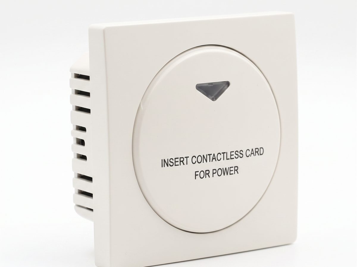
Hotel Key Card Switch — Kontrol Daya Kamar Tamu
Hotel key card switch untuk kontrol daya kamar tamu. Deteksi kartu RFID/IC, masukkan kartu untuk menyalakan daya, penundaan pemadaman saat kartu dilepas. 220V AC, 10A-16A, RS485 atau dry contact. CE RoHS. Pemasok OEM/ODM.
Halaman ini sudah menunjuk ke halaman tersebut sebagai referensi yang direkomendasikan berikutnya.
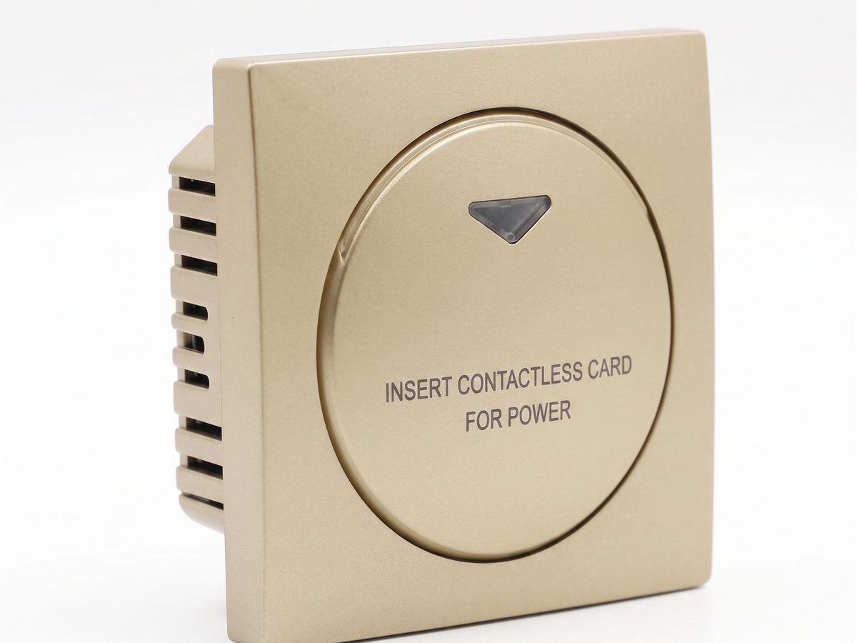
Saklar Hemat Energi Hotel — Kontrol Daya Kamar Masukkan Kartu
Saklar hemat energi hotel: daya nyala saat kartu dimasukkan, mati setelah jeda, integrasi HVAC menghentikan pemborosan kamar kosong. 220V AC, 10A-16A, RS485. CE RoHS.
Halaman ini sudah menunjuk ke halaman tersebut sebagai referensi yang direkomendasikan berikutnya.
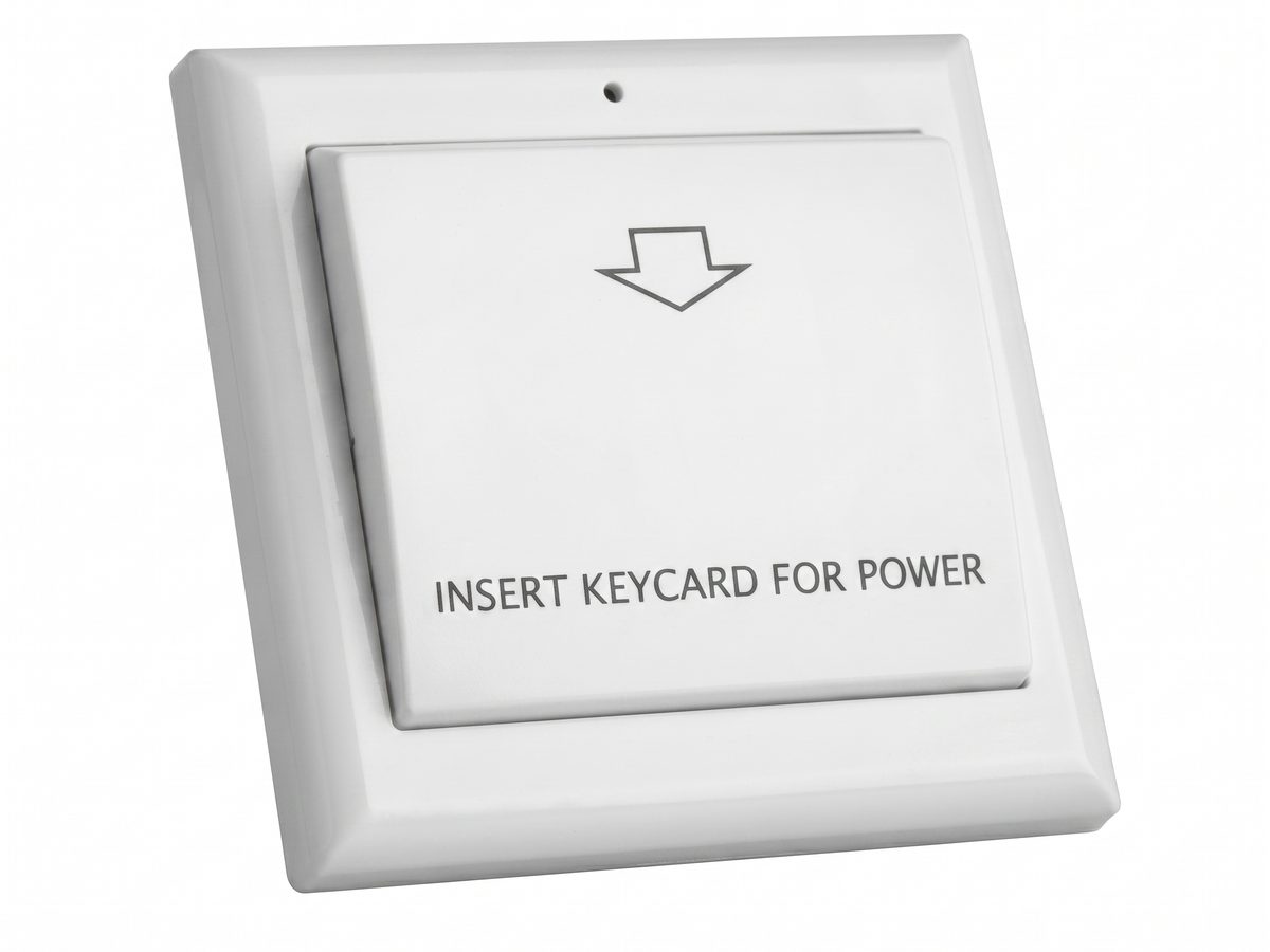
Aksesori Saklar Kartu Kunci — Pelat Muka, Kotak 86, Kontaktor, dan Daya
Aksesori saklar kartu kunci untuk pemasangan kotak 86: pelat muka, dudukan kotak 86, kontaktor untuk HVAC beban tinggi, power supply, dan hub RS485. Pilih aksesori untuk melengkapi setiap proyek saklar kartu kunci kotak 86.
Halaman ini sudah menunjuk ke halaman tersebut sebagai referensi yang direkomendasikan berikutnya.
Solusi terkait
3Kontrol Daya Kamar Hotel dengan Saklar Kartu
Solusi kontrol daya kamar hotel yang praktis untuk mengalihkan pencahayaan, pendingin udara, dan stopkontak kamar tamu dengan kartu kamar resmi.
Halaman ini sudah menunjuk ke halaman tersebut sebagai referensi yang direkomendasikan berikutnya.
Sistem Manajemen Kamar Hotel Berbasis Kartu Listrik
Sistem manajemen kamar hotel praktis untuk mengatur daya listrik kamar melalui saklar kartu kunci, kontaktor, dan aturan operasional yang terdokumentasi.
Halaman tersebut mendukung konteks produk yang sama: Hotel Key Card Switch — Kontrol Daya Kamar Tamu.
Penghematan Energi Hotel dengan Saklar Daya Kamar Tamu
Solusi penghematan energi hotel yang menggunakan daya kamar terkendali kartu untuk mencegah lampu, AC, dan stopkontak terpilih menyala tanpa perlu.
Halaman tersebut mendukung konteks produk yang sama: Hotel Key Card Switch — Kontrol Daya Kamar Tamu.
Artikel blog terkait
3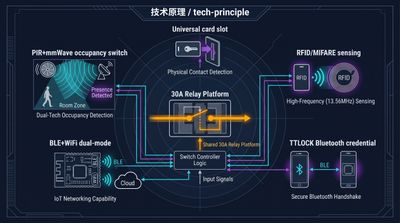
Hotel Key Card Switch: Jenis, Model, dan Cara Memilih
Panduan hotel key card switch mencakup model universal, RFID, TTLOCK, BLE, dan occupancy, serta cara memilih model yang sesuai dengan sistem kartu hotel Anda.
Halaman tersebut mendukung konteks produk yang sama: Hotel Key Card Switch — Kontrol Daya Kamar Tamu.
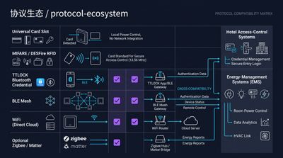
RFID vs NFC untuk Saklar Kartu Kunci Hotel: Pilih Mana?
RFID vs NFC pada saklar kartu kunci hotel berujung pada jangkauan dan penguncian: RFID 125kHz / 13.56MHz (MIFARE, Temic) adalah standar daya kamar hotel…
Halaman tersebut mendukung konteks produk yang sama: Hotel Key Card Switch — Kontrol Daya Kamar Tamu.
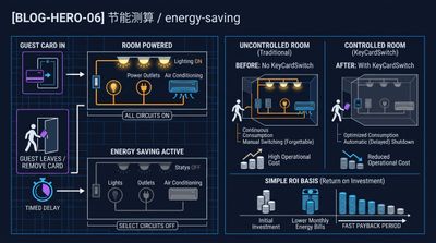
Apa Itu Hotel Key Card Switch dan Cara Hemat Energi Kamar
Hotel key card switch adalah perangkat dinding yang menyalakan listrik kamar saat kartu dimasukkan dan memutusnya saat kartu ditarik, hemat 25–40%…
Halaman tersebut mendukung konteks produk yang sama: Hotel Key Card Switch — Kontrol Daya Kamar Tamu.
Rinci proyek hotel Anda bersama insinyur kami
Kirimkan jumlah kamar, jenis plafon, dan preferensi protokol Anda. Kami akan mengirimkan rencana sampel dan penawaran dalam 24 jam kerja.
- Beralih dari panduan umum ke diskusi produk atau aplikasi.
- Gunakan RFQ saat harga, gambar teknis, MOQ, atau jadwal peluncuran membutuhkan struktur.
- Jaga jalur kontak langsung tetap terlihat untuk klarifikasi cepat dan serah terima.