Guía de instalación de interruptor de tarjeta hotel: cableado paso a paso
Guía de instalación de interruptor de tarjeta hotel para electricistas y mantenimiento: preparación de caja, cableado, conexión de relé, prueba de tarjeta, temporizador y puesta en marcha.
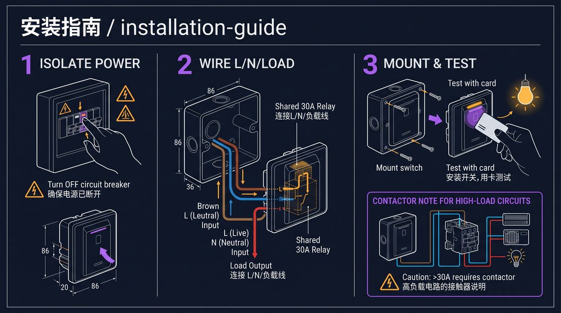
Una guía de instalación de interruptor de tarjeta hotel es un método paso a paso para colocar un interruptor de potencia controlado por tarjeta en una habitación de huéspedes, que cubre la preparación de la caja, el aislamiento eléctrico, el cableado de línea y carga al relé, el montaje del panel empotrado, la prueba de inserción de tarjeta y la verificación del temporizador de retardo. Una guía de instalación de interruptor de tarjeta hotel está escrita para electricistas, personal de mantenimiento e integradores de sistemas que modernizan habitaciones sin recableado mayor, y trata el aislamiento de seguridad en el cuadro de distribución como el primer paso. Una guía de instalación de interruptor de tarjeta hotel guía al instalador a través de la secuencia: confirmar que la caja admite el panel, conectar la alimentación de la habitación en los contactos del relé, tender un par de control de baja corriente al panel, fijar el panel y confirmar que el relé cierra y el retardo funciona antes de que el circuito se abra. Una guía de instalación de interruptor de tarjeta hotel deja claro que el trabajo es un cambio de panel más una conexión de relé, no un recableado de la habitación.
Preparación de la habitación para una guía de instalación de interruptor de tarjeta hotel
La fase de preparación de cualquier guía de instalación de interruptor de tarjeta hotel comienza confirmando el ajuste de la caja de pared y el panel. La unidad más común es un panel empotrado de aproximadamente 86 mm por 86 mm, con un cuerpo trasero de unos 48 mm de profundidad, de los cuales aproximadamente 29 mm quedan dentro de la pared al montarse. Antes de cortar nada, el instalador debe medir la caja unipolar existente — su profundidad, sus orejas de tornillo y su huella — y compararlas con las dimensiones del cuerpo trasero del interruptor. Una guía de instalación de interruptor de tarjeta hotel trata el ajuste de la caja como una verificación previa a la instalación porque un panel que no queda a ras en una caja poco profunda no se montará limpiamente, y cortar una caja más profunda en yeso terminado es mucho más disruptivo que el propio cableado. Si la caja es demasiado poco profunda o está dañada, el instalador debe colocar un extensor de caja o elegir una variante de montaje superficial antes de continuar.
El segundo paso de preparación en una guía de instalación de interruptor de tarjeta hotel es reunir las herramientas y materiales. El instalador necesita un comprobador de tensión o multímetro, destornilladores que coincidan con los tornillos de terminal y fijación, una hoja plana pequeña para los terminales, pelacables, cortacables y el herraje de montaje del panel. Los materiales incluyen conductores dimensionados correctamente para los contactos del relé, un par de control al panel, prensaestopas o gomas donde el cable entra en la caja, y cualquier placa adaptadora necesaria para la caja. Una guía de instalación de interruptor de tarjeta hotel aconseja disponer todo esto antes de empezar para que el instalador no sea interrumpido a medio conectar, y advierte que cada conexión debe hacerse con el circuito aislado.
El tercer paso de preparación es identificar el circuito de la habitación y la ruta de la carga. El instalador debe saber qué interruptor o fusible en el cuadro de distribución alimenta esta habitación, y debe rastrear cómo la alimentación de fase llega a la posición del interruptor y cómo los conductores de carga continúan hacia las luces, los enchufes y el termostato del aire acondicionado. Una guía de instalación de interruptor de tarjeta hotel hace que el instalador trace el cableado existente en un croquis o fotografía antes de tocar nada, porque la alimentación de la habitación debe pasar por los contactos del relé mientras solo un par de control va al panel. Malentender qué cable es la alimentación entrante y cuál es la carga saliente es la fuente más común de una instalación que alimenta el panel pero no conmuta la habitación.
El cuarto paso de preparación es confirmar la tensión de alimentación y la polaridad. El instalador debe verificar que la tensión medida en la caja coincide con la entrada nominal del interruptor, típicamente 110 V o 180–250 V CA, antes de conectar. Una guía de instalación de interruptor de tarjeta hotel insiste en una comprobación de tensión en vivo con un medidor en lugar de confiar en la etiqueta, porque una alimentación mal identificada o una tensión parásita pueden dañar el panel o crear un riesgo de descarga. La polaridad del conductor de fase debe confirmarse si los terminales de la unidad están marcados, porque conectar la fase en el terminal equivocado es una causa frecuente de un panel que zumba, no conmuta o acaba fallando.
El quinto paso de preparación es decidir si se usará un relé integrado o un relé externo. Si el interruptor tiene un relé integrado, el instalador tiende la alimentación de la habitación directamente a los terminales de carga del panel. Si el modelo necesita un relé externo o contactor porque la carga de la habitación supera la capacidad interna, el instalador debe localizar un punto de montaje para ese relé, cerca del panel o en el cuadro de distribución, y tender un par de control entre ambos. Una guía de instalación de interruptor de tarjeta hotel trata esta decisión como parte de la preparación para que el relé adecuado, el cable adecuado y la posición de montaje adecuada estén listos antes de aislar la alimentación.
Aislamiento de seguridad en una guía de instalación de interruptor de tarjeta hotel
La seguridad es el primer mandamiento de cualquier guía de instalación de interruptor de tarjeta hotel, y comienza aislando el circuito de la habitación en el cuadro de distribución. Antes de abrir cualquier tapa, el instalador debe desconectar el interruptor automático o retirar el fusible que alimenta la habitación y bloquear o señalizar el punto de aislamiento para que nadie lo reenergice durante el trabajo. Una guía de instalación de interruptor de tarjeta hotel trata el bloqueo-señalización como innegociable, porque un ayudante o un electricista que regresa y acciona el interruptor equivocado mientras una mano está en la caja puede causar una lesión grave. El aislamiento debe confirmarse con un comprobador de tensión en los conductores en la posición del interruptor, no asumirse desde la posición del interruptor.
El segundo paso de seguridad en una guía de instalación de interruptor de tarjeta hotel es verificar tensión cero en los terminales exactos a trabajar. Puede haber tensión incluso con el interruptor apagado si una alimentación es compartida, si un circuito diferente pasa por la caja, o si hay una capacitancia parásita en el cable. El instalador debe probar entre fase y neutro, entre fase y tierra, y entre fase y fase en la caja y no encontrar tensión antes de conectar. Una guía de instalación de interruptor de tarjeta hotel aconseja probar en los terminales, no solo en un punto remoto, porque un neutro compartido o una alimentación mal cableada en otro lugar puede dejar la caja viva.
El tercer paso de seguridad es trabajar en seco y limpio. Las habitaciones de huéspedes son secas, pero el instalador debe comprobar igualmente si hay entrada de agua, condensación o fugas cerca de la caja, y posponer el trabajo si hay humedad. La zona de trabajo debe mantenerse libre de polvo y residuos para que nada caiga en la caja abierta durante la conexión. Una guía de instalación de interruptor de tarjeta hotel también señala que el instalador no debe trabajar en el circuito mientras los electrodomésticos de la habitación o el aire acondicionado permanezcan energizados de forma que puedan retroalimentar el cableado de control, y debe asegurar que todas las cargas conectadas estén apagadas durante la fase de cableado.
El cuarto paso de seguridad es usar protección personal y de componentes correctamente dimensionada. El instalador debe trabajar con herramientas aisladas, apoyarse en una superficie no conductiva donde sea posible, y usar un comprobador de tensión con fusible o adecuadamente dimensionado. Los conductores y terminales deben estar dimensionados para la corriente que transportarán, y el panel y el relé deben estar dimensionados para la tensión de alimentación de la habitación. Una guía de instalación de interruptor de tarjeta hotel enfatiza que elegir componentes dimensionados por encima de la carga y tensión medidas, en lugar de en el límite exacto, deja un margen de seguridad que protege la instalación durante años de servicio.
La quinta consideración de seguridad en una guía de instalación de interruptor de tarjeta hotel es no introducir nuevos puntos únicos de fallo. El instalador debe evitar encadenar cargas en los contactos del relé de forma que sobrecargue una conexión, debe apretar cada terminal a su par especificado, y debe volver a comprobar cada conexión después de aplicar la carga de la habitación. Es más seguro conectar cada circuito de habitación en su propio contacto de relé donde la unidad proporciona múltiples canales que amontonar varios circuitos en un terminal, porque un terminal suelto o sobrecargado es una fuente común de calor y fallo prematuro.
Guía de instalación de interruptor de tarjeta hotel: cableado de la alimentación de la habitación al relé
El paso eléctrico central en una guía de instalación de interruptor de tarjeta hotel es conectar la alimentación de la habitación en los contactos del relé. El instalador identifica primero la alimentación de fase entrante desde el cuadro de distribución y la carga saliente que va a las luces, enchufes y aire acondicionado de la habitación. El contacto común del relé acepta la fase entrante, y el contacto normalmente abierto conecta al lado de la carga, de modo que cuando el relé cierra, la potencia fluye de la alimentación a través de los contactos a la habitación. Una guía de instalación de interruptor de tarjeta hotel hace que el instalador confirme la identificación de los contactos en el relé — común (C), normalmente abierto (NA) y normalmente cerrado (NC) — y advierte que cablear en el contacto normalmente cerrado por error deja la habitación alimentada cuando la tarjeta está ausente.
El conductor neutro se maneja según el diseño del interruptor. En muchos interruptores de tarjeta, el lector y la bobina del relé se alimentan desde el lado de la línea y el neutro pasa a la carga sin cambios, así que el instalador conecta el neutro directamente de la alimentación a la carga de la habitación. Algunos diseños requieren un neutro en el panel para la electrónica. Una guía de instalación de interruptor de tarjeta hotel dice que el tratamiento correcto del neutro está indicado en el diagrama de cableado, y el instalador debe seguirlo exactamente, porque dejar un neutro desconectado puede impedir que el interruptor funcione o dejar el circuito inseguro en un diseño de neutro compartido.
El conductor de tierra se conecta al terminal de tierra del panel y a cualquier parte conectada a tierra del cuerpo trasero. Una guía de instalación de interruptor de tarjeta hotel trata la toma de tierra como obligatoria donde la unidad proporciona un terminal de tierra, porque la placa trasera metálica y cualquier parte conductora expuesta deben estar unidas para proteger contra un fallo. La tierra debe conectarse firmemente y ser continua hasta la distribución conectada a tierra de la habitación. Donde la caja existente no tiene tierra, el instalador debe señalar la deficiencia en lugar de conectar el panel sin tierra, porque un fallo en un panel sin tierra puede energizar las partes metálicas.
El par de control entre el interruptor y cualquier relé externo se tiende entonces. Si la unidad acciona un relé externo, el instalador tiende un par de baja corriente desde la salida de control del panel a los terminales de la bobina del relé. Este par transporta solo la corriente de accionamiento de la bobina, unos pocos miliamperios a unos cientos de miliamperios, así que puede ser de calibre menor que la alimentación de la habitación, pero debe estar protegido y tendido lejos de bordes dañados o afilados. Una guía de instalación de interruptor de tarjeta hotel hace que el instalador etiquete claramente el par de control para que un futuro técnico no lo confunda con un conductor de carga y persiga un fallo fantasma.
Una vez que todos los conductores están conectados, el instalador aprieta cada terminal a su par especificado y vuelve a comprobar que ningún hilo de un conductor multihilo está suelto o pellizcado contra un terminal adyacente. Una guía de instalación de interruptor de tarjeta hotel enfatiza esta re-comprobación porque un conductor suelto es invisible a una inspección visual y es una causa principal de contacto intermitente, calor y fallo eventual. Después de apretar, el instalador debe tirar suavemente de cada conductor para confirmar que está firmemente sujeto antes de montar el panel, porque reconectar después de que el panel está en su sitio es mucho más incómodo.
Guía de instalación de interruptor de tarjeta hotel: conexión del panel de interruptor y circuito de control
Con la alimentación y la carga conectadas, una guía de instalación de interruptor de tarjeta hotel pasa a conectar los terminales de control del panel. El panel tiene un pequeño conjunto de terminales: el lado de entrada o alimentación del lector, la salida de accionamiento del relé, y cualquier terminal para la sección de retardo o anulación. El instalador conecta la alimentación de fase del panel a la alimentación entrante, conecta su neutro y tierra según el diagrama, y conecta la salida de control del relé en la bobina del relé o la entrada del relé integrado del panel. Una guía de instalación de interruptor de tarjeta hotel aconseja organizar los conductores en la caja para que el panel se deslice sin pellizcar, y dejar suficiente holgura para que el panel pueda retirarse luego para servicio sin tensar los terminales.
El relé integrado del panel, cuando lo lleva, recibe la alimentación de la habitación directamente en sus terminales de carga. En ese caso el instalador conecta la fase entrante en el común del relé y la carga saliente de la habitación en el contacto normalmente abierto, ambos dentro del cuerpo trasero. Una guía de instalación de interruptor de tarjeta hotel señala que una unidad con relé integrado hace la conexión autocontenida y elimina la necesidad de un relé remoto, pero también significa que el relé está dentro de la caja empotrada, así que la caja debe tener espacio para el relé más el cableado sin saturación. Si la caja es justa, el instalador debe reencaminar los conductores para evitar curvas pronunciadas contra el cuerpo del relé.
Los ajustes de retardo y anulación se configuran durante esta fase para modelos que lo permiten. Donde la unidad tiene un jumper, un pequeño interruptor rotativo o un interruptor DIP para el valor de retardo, el instalador lo ajusta al valor elegido por el establecimiento, comúnmente 15 segundos. Donde existe una anulación manual para limpieza, el instalador confirma que está en la posición inicial correcta, normalmente controlada por tarjeta en lugar de permanentemente encendida. Una guía de instalación de interruptor de tarjeta hotel hace que el instalador configure estos controles ahora, con el diagrama en mano, porque ajustarlos después de montar la cara es incómodo y fácilmente se olvida, dejando la habitación con un retardo no intencionado o un circuito permanentemente energizado.
La conexión del lector se confirma antes del montaje final. La cabeza del lector de tarjeta, ya sea una ranura magnética o una zona de lectura RFID, se conecta al controlador del panel ya sea a través de un cable plano fijo o un conector enchufable. El instalador debe insertar el conector completamente y verificar que encaja, porque un conector de lector parcialmente insertado es un fallo intermitente clásico que hace que el interruptor funcione solo intermitentemente. Una guía de instalación de interruptor de tarjeta hotel aconseja confirmar que el lector es detectado observando el comportamiento del indicador del panel durante la prueba, ya que la mayoría de unidades encienden una lámpara cuando el lector y el controlador se comunican.
Las entradas de cableado se sellan antes de fijar el panel. Cualquier knockout o entrada no usada debe cerrarse para que polvo e insectos no entren en la caja, y un prensaestopas o goma debe proteger el cable donde pasa por el cuerpo trasero. Una guía de instalación de interruptor de tarjeta hotel trata este sellado como un pequeño pero real paso de fiabilidad, porque una caja sellada mantiene la electrónica limpia, previene la intrusión de humedad y evita las llamadas de servicio que una caja comprometida invita con el tiempo.
Guía de instalación de interruptor de tarjeta hotel: montaje del panel empotrado y fijación del cuerpo trasero
El montaje comienza, en una guía de instalación de interruptor de tarjeta hotel, colocando el cuerpo trasero en la caja de pared. El cuerpo trasero se desliza en la caja unipolar, con su cableado tendido por las entradas y sus agujeros de tornillo alineados con las orejas de la caja. El instalador baja el cuerpo, asegurándose de que los conductores no queden atrapados entre el cuerpo y la pared de la caja, y que la flexión del cable no tire de un terminal suelto. Una guía de instalación de interruptor de tarjeta hotel hace que el instalador asiente el cuerpo completamente para que su brida de montaje quede a ras contra la superficie de la pared, que es el punto en que los 29 mm de empotramiento del panel llenan la profundidad de la caja limpiamente.
El cuerpo trasero se fija entonces. La mayoría de unidades se fijan a las orejas de la caja con dos tornillos de montaje, y algunas también se fijan a un marco o directamente a la pared. El instalador aprieta los tornillos uniformemente, alternando entre los dos o cuatro puntos de fijación, para que el cuerpo asiente cuadrado y no se incline. Una guía de instalación de interruptor de tarjeta hotel advierte contra el apriete excesivo, que puede agrietar un cuerpo trasero de plástico o dañar el montaje, y contra el apriete insuficiente, que deja el panel suelto y tambaleante. El objetivo es un asiento firme y nivelado con la brida pegada a la pared en todos los lados.
La placa frontal se encaja o atornilla entonces sobre el cuerpo trasero. La cara se bloquea sobre la brida, cubriendo los tornillos y la caja, y lleva la ranura de tarjeta o la zona de lectura RFID y cualquier lámpara indicadora. El instalador alinea la cara para que la ranura de tarjeta coincida con el lector y la placa quede nivelada con la pared, luego la bloquea en su sitio. Una guía de instalación de interruptor de tarjeta hotel señala que la cara debe encajar limpiamente con un clic o un tornillo asentado, y que una cara que no vuelve a asentar tras la retirada suele indicar un conductor atrapado o un cuerpo trasero ligeramente desalineado que debe corregirse antes de terminar la habitación.
Después de colocar la cara, el instalador comprueba la alineación y el espacio de la ranura de tarjeta. La tarjeta debe deslizarse en una ranura magnética con resistencia ligera y uniforme, y la zona de lectura RFID debe ser accesible en la cara sin obstrucción. Una guía de instalación de interruptor de tarjeta hotel hace que el instalador inserte y retire una tarjeta varias veces inmediatamente después del montaje para confirmar que la ranura no está bloqueada y el lector opera a través de la cara, porque una desalineación sutil es mucho más fácil de corregir antes de que la cara se selle y la habitación se entregue.
Finalmente en la fase de montaje, el instalador verifica que el panel está nivelado y que la cara no sobresale ni se mueve. El panel terminado debe quedar plano y estable, sin movimiento al insertar una tarjeta o presionar el indicador. Una guía de instalación de interruptor de tarjeta hotel trata un acabado empotrado estable, nivelado y a ras como parte del entregable, porque un panel torcido o suelto se lee como una mala instalación incluso cuando eléctricamente funciona perfectamente, e invita al huésped a manipular un dispositivo que no parece bien instalado.
Guía de instalación de interruptor de tarjeta hotel: conexión y montaje de un relé o contactor externo
Para habitaciones cuya carga supera la capacidad del relé interno del interruptor, una guía de instalación de interruptor de tarjeta hotel cubre la conexión de relé externo en detalle. El relé externo o contactor se monta en un punto adecuado, ya sea en un carril DIN en el cuadro de distribución o en una placa trasera cerca del interruptor. La alimentación de la habitación se tiende a través de los contactos principales del contactor, y el par de control de baja corriente del interruptor se conecta a la bobina del contactor. Una guía de instalación de interruptor de tarjeta hotel hace que el instalador confirme que la tensión de bobina del contactor coincide con la salida de control del interruptor, porque un desajuste significa que la bobina nunca atrae y la habitación nunca se alimenta.
El cableado de los contactos principales del contactor sigue la misma lógica de común y normalmente abierto que el relé interno. La fase entrante aterriza en el lado de línea del contactor, la carga saliente de la habitación aterriza en el lado de carga, y cuando la bobina se energiza los contactos cierran para completar el circuito de la habitación. Una guía de instalación de interruptor de tarjeta hotel confirma que el contactor se selecciona para que su capacidad de contactos principales supere la carga medida de la habitación con margen, y que su bobina acepte la señal de control del interruptor, ya sea que sea la tensión de línea o una salida de CC de baja tensión según el modelo.
El cableado de control desde el interruptor a la bobina del contactor es la parte más sensible a una conexión errónea. El instalador tiende un par claramente etiquetado desde la salida de control del panel a los terminales de la bobina del contactor, observando la polaridad si la bobina es de CC o si la unidad la marca. Una guía de instalación de interruptor de tarjeta hotel hace que el instalador evite tender el par de control junto a cables de alta corriente donde sea posible, o use un par apantallado si deben ir juntos, para prevenir que el ruido inducido conmute la bobina. El circuito de control debe estar fusionado o protegido según el diagrama, porque un cortocircuito en el par de control podría alimentar un fallo en el panel.
El contactor debe montarse para disipar su calor. Un contactor que transporta corriente produce algo de calor en su bobina y contactos, así que necesita espacio y ventilación en lugar de enterrarse apretado en un espacio cerrado. Una guía de instalación de interruptor de tarjeta hotel aconseja montar el contactor con algo de espacio de aire, fijarlo firmemente para que no pueda vibrar o balancear, y dejar sus terminales accesibles para servicio. Un contactor recalentado o suelto acorta la vida de bobina y contactos y es más difícil de servir cuando eventualmente necesita atención.
Finalmente, el instalador etiqueta claramente el relé externo. Una nota en o junto al contactor indicando que es el relé de tarjeta para un número de habitación específico permite al mantenimiento encontrarlo rápido y evita que alguien lo recablee por error durante trabajos posteriores. Una guía de instalación de interruptor de tarjeta hotel trata el etiquetado como parte estándar de una instalación profesional, porque un relé sin etiqueta en un cuadro de distribución es una suposición costosa para el siguiente técnico, y uno etiquetado convierte un diagnóstico en un trabajo de dos minutos.
Guía de instalación de interruptor de tarjeta hotel: prueba de inserción de tarjeta y operación del relé
La prueba es el punto donde una guía de instalación de interruptor de tarjeta hotel confirma que el cableado realmente funciona, y siempre debe hacerse en una lámpara de prueba antes de entregar la habitación. El instalador conecta una lámpara de prueba simple o una pequeña carga resistiva en el circuito conmutado, aísla la carga real de la habitación, y empieza la prueba con el circuito aún controlado desde un punto seguro. Una guía de instalación de interruptor de tarjeta hotel insiste en la carga de prueba en la primera prueba porque previene que un error de cableado energice los circuitos reales de la habitación inesperadamente, y porque aísla el comportamiento del interruptor de cualquier fallo de carga.
La primera prueba es la prueba de inserción de tarjeta. Con una tarjeta válida del medio correcto insertada en la ranura o presentada al lector, el indicador del panel debe cambiar y el relé debe cerrar en aproximadamente un segundo, energizando la lámpara de prueba. Si la lámpara no se enciende, el instalador comprueba el medio de la tarjeta, la conexión del lector, el cableado del relé y la alimentación del panel en ese orden. Una guía de instalación de interruptor de tarjeta hotel aconseja solucionar problemas paso a paso: tarjeta reconocida, señal de lectura llega al controlador, controlador acciona el relé, contactos cierran, carga conduce, y confirmando cada paso antes de pasar al siguiente.
La segunda prueba es la prueba de retardo. Con la tarjeta retirada, el relé debe permanecer cerrado durante el retardo configurado, típicamente 15 segundos, luego abrir y cortar la lámpara de prueba. El instalador cronometra esto con un cronómetro o el indicador del panel y confirma que el retardo coincide con el valor configurado. Una guía de instalación de interruptor de tarjeta hotel hace que el instalador repita esta prueba varias veces, y también reinserte la tarjeta durante la ventana de retardo para confirmar que el interruptor re-energiza sin conmutar, porque un interruptor que conmuta erróneamente en una reinserción es confuso y debe corregirse antes de la entrega.
La tercera prueba es la comprobación de anulación, donde la unidad tiene una anulación manual para limpieza. El instalador acciona la anulación y confirma que la lámpara de prueba se energiza sin tarjeta, luego restablece la anulación y confirma que el interruptor vuelve a operación controlada por tarjeta y la lámpara se corta en retardo tras retirar la tarjeta. Una guía de instalación de interruptor de tarjeta hotel trata una anulación funcional como requisito solo si el establecimiento la usa para limpieza, pero debe verificarse de todos modos para conocer su comportamiento.
La cuarta prueba es una comprobación de estabilidad y operación repetida. El instalador inserta y retira la tarjeta quizás veinte veces y confirma que el relé abre y cierra fiablemente en cada ciclo sin atascarse o rebotar, y que el panel no se sobrecalienta. Una guía de instalación de interruptor de tarjeta hotel aconseja este pase de resistencia en una muestra antes de comprometer toda la propiedad, porque los fallos que revela — un terminal suelto, un asiento de lector intermitente, un relé marginal — son exactamente los que de otro modo surgirían en una habitación de huésped real.
Guía de instalación de interruptor de tarjeta hotel: verificación del temporizador de retardo y ajuste del parámetro
Configurar y verificar el temporizador de retardo es su propio paso en una guía de instalación de interruptor de tarjeta hotel. La mayoría de unidades seleccionan el retardo con un jumper, un pequeño interruptor rotativo, un interruptor DIP o un potenciómetro a bordo, y el instalador lo ajusta al valor que el establecimiento eligió, comúnmente 15 segundos. El ajuste debe hacerse con la unidad documentada, porque la posición del selector es fácil de leer mal contra una pequeña leyenda impresa. Una guía de instalación de interruptor de tarjeta hotel hace que el instalador ajuste el retardo como parte de la fase de cableado, luego lo verifique en la fase de prueba para que los dos no queden separados por un ajuste olvidado.
El retardo se comporta como un intervalo fijo desde el momento en que la tarjeta se retira. El instalador debe confirmar que el temporizador arranca en la retirada de la tarjeta y no en otro evento, y que todos los circuitos conmutados caen juntos cuando el temporizador expira. Una guía de instalación de interruptor de tarjeta hotel señala que algunas unidades de dos canales temporizan los canales de iluminación y aire acondicionado de forma distinta, dejando que la iluminación caiga tras un retardo corto mientras un dispositivo controlado se apaga más lentamente, y el instalador debe verificar el retardo de cada canal contra la configuración esperada.
Si el establecimiento tiene múltiples tipos de habitación o diferentes hábitos de limpieza, el retardo puede necesitar diferir por habitación. Una guía de
A hotel key card switch installation guide is a step-by-step method for fitting a card-controlled power switch into a guest room, covering box preparation, electrical isolation, wiring the line and load to the relay, mounting the flush panel, testing card insertion, and verifying the delay-off timer. A hotel key card switch installation guide is written for electricians, maintenance staff, and system integrators who retrofit rooms without major rewiring, and it treats safety isolation at the distribution point as the first step. A hotel key card switch installation guide leads the installer through the sequence: confirming the box fits the panel, landing the room feed on the relay contacts, routing a low-current control pair to the plate, securing the panel, and confirming the relay closes and the delay-off works before the circuit opens. A hotel key card switch installation guide makes clear the job is a panel swap plus a relay connection, not a rewire of the room.
Preparing the Room for a Hotel Key Card Switch Installation Guide
The preparation phase of any hotel key card switch installation guide begins with confirming the wall box and the panel fit. The most common unit is a flush panel of roughly 86mm by 86mm, with a back body about 48mm deep, of which roughly 29mm sits inside the wall when mounted. Before cutting anything, the installer should measure the existing single-gang box — its depth, its screw ears, and its footprint — and compare them to the switch's back-body dimensions. A hotel key card switch installation guide treats box fit as a pre-install verification because a panel that does not sit flush in a shallow box will not mount cleanly, and cutting a deeper box in finished plaster is far more disruptive than the wiring itself. If the box is too shallow or damaged, the installer must either fit a box extender or choose a surface-mount variant before proceeding.
The second preparation step in a hotel key card switch installation guide is gathering the tools and materials. The installer needs a voltage tester or multimeter, screwdrivers matching the terminal and fixing screws, a small flat blade for the terminals, wire strippers, cable cutters, and the panel's mounting hardware. The materials include properly sized conductors for the relay contacts, a control pair to the panel, cable glands or grommets where the cable enters the box, and any adapter plates needed for the box. A hotel key card switch installation guide advises laying these out before starting so the installer is not interrupted mid-connection, and cautions that every connection must be made with the circuit isolated.
The third preparation step is identifying the room circuit and the load path. The installer must know which breaker or fuse at the distribution point feeds this room, and must trace how the live feed reaches the switch position and how the load leads onward to the lights, the sockets, and the air-conditioning thermostat. A hotel key card switch installation guide has the installer map the existing wiring on a sketch or photograph before touching anything, because the room feed must be routed through the relay contacts while only a control pair goes to the panel. Misunderstanding which cable is the incoming feed and which is the outgoing load is the most common source of an installation that powers the panel but does not switch the room.
The fourth preparation step is confirming the supply voltage and polarity. The installer should verify the measured voltage at the box matches the switch's rated input, typically 110V or 180–250V AC, before connection. A hotel key card switch installation guide insists on a live-voltage check with a meter rather than trusting the label, because a misidentified feed or a stray voltage can damage the panel or create a shock hazard. The live conductor polarity should be confirmed if the unit's terminals are marked, because landing the line on the wrong terminal is a frequent cause of a panel that hums, fails to switch, or eventually fails.
The fifth preparation step is deciding whether a built-in relay or an external relay will be used. If the switch has a built-in relay, the installer routes the room feed directly to the panel's load terminals. If the model needs an external relay or contactor because the room load exceeds the internal rating, the installer must locate a mounting point for that relay, close to the panel or at the distribution board, and run a control pair between the two. A hotel key card switch installation guide treats this decision as part of preparation so that the right relay, the right cable, and the right mounting position are ready before the power is isolated.
Safety Isolation in a Hotel Key Card Switch Installation Guide
Safety is the first commandment of any hotel key card switch installation guide, and it starts with isolating the room circuit at the distribution point. Before any cover is opened, the installer must switch off the circuit breaker or withdraw the fuse feeding the room and lock or tag the isolation point so no one re-energizes it during work. A hotel key card switch installation guide treats lockout-tagout as non-negotiable, because a helper or a returning electrician who flips the wrong breaker while a hand is in the box can cause a serious injury. The isolation must be confirmed with a voltage tester on the conductors at the switch position, not assumed from the breaker position.
The second safety step in a hotel key card switch installation guide is verifying zero voltage at the exact terminals to be worked. Voltage can be present even with the breaker off if a feed is shared, if a different circuit wanders through the box, or if there is a stray capacitance in the cable. The installer should test between live and neutral, between live and earth, and between live and live at the box and find no voltage before connecting. A hotel key card switch installation guide advises testing at the terminals, not just at a remote point, because a shared neutral or miswired feed elsewhere can leave the box live.
The third safety step is working dry and clean. Guest rooms are dry, but the installer should still check for water ingress, condensation, or leaks near the box, and postpone the work if moisture is present. The work area should be kept free of dust and debris so nothing falls into the open box during connection. A hotel key card switch installation guide also notes that the installer should not work on the circuit while the room's appliances or the air-conditioning remain energized in a way that could back-feed the control wiring, and should ensure all connected loads are off during the wiring phase.
The fourth safety step is using correctly rated personal and component protection. The installer should work with insulated tools, stand on a non-conductive surface where possible, and use a fused or appropriately rated voltage tester. The conductors and terminals must be rated for the current they will carry, and the panel and relay must be rated for the room's supply voltage. A hotel key card switch installation guide emphasizes that choosing components rated above the measured load and supply, rather than at the exact rating, leaves a safety margin that protects the installation over years of service.
The fifth safety consideration in a hotel key card switch installation guide is not introducing new single-point failures. The installer should avoid daisy-chaining loads on the relay contacts in a way that overloads one connection, should tighten every terminal to its specified torque, and should re-check each connection after the room's load is applied. It is safer to land each room circuit on its own relay contact where the unit provides multiple channels than to crowd several circuits onto one terminal, because a loose or overloaded single terminal is a common source of heat and premature failure.
Hotel Key Card Switch Installation Guide: Wiring the Room Feed to the Relay
The core electrical step in a hotel key card switch installation guide is landing the room feed on the relay contacts. The installer first identifies the incoming live feed from the distribution point and the outgoing load that leads to the room's lights, sockets, and air-conditioning. The relay's common contact accepts the incoming live, and the normally-open contact connects to the load side, so that when the relay closes, power flows from the feed through the contacts to the room. A hotel key card switch installation guide has the installer confirm the contact identification on the relay — common (C), normally open (NO), and normally closed (NC) — and warns that wiring into the normally-closed contact by mistake leaves the room powered when the card is absent.
The neutral conductor is handled according to the switch's design. On many key card switches, the reader and relay coil draw from the line side and the neutral is passed through to the load unchanged, so the installer connects the neutral straight through from the supply to the room load. A few designs require a neutral at the panel for the electronics. A hotel key card switch installation guide says the correct neutral treatment is stated on the wiring diagram, and the installer should follow it exactly, because leaving a neutral unconnected can prevent the switch from operating or leave the circuit unsafe on a shared-neutral design.
The earth conductor is connected to the panel's earth terminal and to any earthed parts of the back body. A hotel key card switch installation guide treats earthing as mandatory where the unit provides an earth terminal, because the metal back plate and any exposed conductive parts must be bonded to protect against a fault. The earth should be landed securely and should be continuous to the room's earthed distribution. Where the existing box has no earth, the installer should flag the deficiency rather than connect the panel un-ear, because a fault on an un-ear panel can energize the metalwork.
The control pair between the switch and any external relay is then routed. If the unit drives an external relay, the installer runs a low-current pair from the panel's control output to the relay coil terminals. This pair carries only the coil drive current, a few milliamps to a few hundred milliamps, so it can be smaller-gauge than the room feed, but it must be protected and routed away from damaged or sharp edges. A hotel key card switch installation guide has the installer label the control pair clearly so a future technician does not mistake it for a load conductor and chase a phantom fault.
Once all conductors are landed, the installer tightens every terminal to its specified torque and double-checks that no strand of a multi-strand conductor is loose or pinched against an adjacent terminal. A hotel key card switch installation guide emphasizes this re-check because a loose conductor is invisible to a visual glance and is a leading cause of intermittent contact, heat, and eventual failure. After tightening, the installer should gently tug each conductor to confirm it is held firmly before mounting the panel, because reconnecting after the panel is in place is far more awkward.
Hotel Key Card Switch Installation Guide: Connecting the Switch Panel and Control Circuit
With the feed and load landed, a hotel key card switch installation guide moves to connecting the panel's control terminals. The panel has a small set of terminals: the input side or the reader supply, the relay drive output, and any terminals for the delay or override section. The installer connects the panel's line supply to the live feed, connects its neutral and earth per the diagram, and lands the relay control output on the relay coil or the panel's own integrated relay input. A hotel key card switch installation guide advises organizing the conductors in the box so the panel slides in without pinching, and leaving enough slack that the panel can be withdrawn later for service without straining the terminals.
The panel's integrated relay, where fitted, receives the room feed directly on its load terminals. In that case the installer lands the incoming live on the relay common and the outgoing room load on the normally-open contact, both within the back body. A hotel key card switch installation guide notes that an integrated-relay unit makes the connection self-contained and removes the need for a remote relay, but it also means the relay is inside the flush box, so the box must have room for the relay plus the wiring without overcrowding. If the box is tight, the installer should re-route the conductors to avoid sharp bends against the relay body.
The delay and override settings are set during this phase for models that allow adjustment. Where the unit has a jumper, a small rotary switch, or a dip switch for the delay-off value, the installer sets it to the value chosen by the property, commonly 15 seconds. Where a manual override for housekeeping exists, the installer confirms it is in the correct starting position, normally card-controlled rather than permanently on. A hotel key card switch installation guide has the installer set these controls now, with the diagram in hand, because adjusting them after the face is mounted is awkward and easily forgotten, leaving the room with an unintended delay or a permanently energized circuit.
The reader connection is confirmed before final mounting. The card reader head, whether a magnetic slot or an RFID read zone, connects to the panel's controller either through a fixed ribbon or a pluggable connector. The installer should seat the connector fully and verify it latches, because a partially seated reader connector is a classic intermittent fault that makes the switch work only intermittently. A hotel key card switch installation guide advises confirming the reader is detected by observing the panel's indicator behavior during the test, since most units light a lamp when the reader and controller are communicating.
The wiring entries are sealed before the panel is secured. Any knockout or entry not used should be closed so dust and insects cannot enter the box, and gland or grommet should protect the cable where it passes through the back body. A hotel key card switch installation guide treats this sealing as a small but real reliability step, because a sealed box keeps the electronics clean, prevents moisture intrusion, and avoids the service calls that a compromised box invites over time.
Hotel Key Card Switch Installation Guide: Mounting the Flush Panel and Securing the Back Body
Mounting begins, in a hotel key card switch installation guide, with fitting the back body into the wall box. The back body slides into the single-gang box, with its wiring routed through the entries and its screw holes aligned to the box's ears. The installer lowers the body in, making sure the conductors are not trapped between the body and the box wall, and that the flex of the cable does not pull a terminal loose. A hotel key card switch installation guide has the installer seat the body fully so its mounting flange sits flush against the wall surface, which is the point at which the panel's 29mm embedment fills the box depth cleanly.
The back body is then secured. Most units fix to the box ears with two mounting screws, and some also fix to a frame or directly to the wall. The installer tightens the screws evenly, alternating between the two or four fixing points, so the body seats square and does not tilt. A hotel key card switch installation guide warns against over-tightening, which can crack a plastic back body or strip the mount, and against under-tightening, which leaves the panel loose and wobbly. The goal is a firm, level seat with the flange held flat against the wall on all sides.
The face plate is then clipped or screwed over the back body. The face locks over the flange, covering the screws and the box, and carries the card slot or the RFID read zone and any indicator lamp. The installer aligns the face so the card slot lines up with the reader and so the plate is level with the wall, then locks it in place. A hotel key card switch installation guide notes that the face should engage cleanly with a click or a seated screw, and that a face that will not seat again after removal usually signals a trapped conductor or a slightly misaligned back body that must be corrected before the room is finished.
After the face is on, the installer checks the alignment and clearance of the card slot. The card should slide into a magnetic slot with light, even resistance, and the RFID read zone should be accessible on the face without obstruction. A hotel key card switch installation guide has the installer insert and withdraw a card several times immediately after mounting to confirm the slot is not blocked and the reader operates through the face, because a subtle misalignment is far easier to fix before the face is sealed and the room is handed over.
Finally at the mounting stage, the installer verifies the panel is level and that the face does not protrude or rock. The finished panel should sit flat and stable, with no movement when a card is inserted or the indicator is pressed. A hotel key card switch installation guide treats a stable, level, flush-mount finish as part of the deliverable, because a crooked or loose panel reads as a poor installation even when electrically it works perfectly, and it invites the guest to tamper with a device that does not look well-fitted.
Hotel Key Card Switch Installation Guide: Connecting and Mounting an External Relay or Contactor
For rooms whose load exceeds the switch's internal relay rating, a hotel key card switch installation guide covers external relay connection in detail. The external relay or contactor is mounted at a suitable point, either on a DIN rail at the distribution board or on a backplate near the switch. The room feed is routed through the contactor's main contacts, and the switch's low-current control pair connects to the contactor coil. A hotel key card switch installation guide has the installer confirm the contactor's coil voltage matches the switch's control output, because a mismatch means the coil never pulls in and the room never powers.
The contactor's main contact wiring follows the same common-and-normally-open logic as the internal relay. The incoming live lands on the contactor's line side, the outgoing room load lands on the load side, and when the coil is energized the contacts close to complete the room circuit. A hotel key card switch installation guide confirms the contactor is selected so its main contact rating exceeds the measured room load with margin, and that its coil accepts the switch's control signal, whether that is the line voltage or a low-voltage DC output depending on the model.
The control wiring from the switch to the contactor coil is the piece most sensitive to wrong connection. The installer routes a clearly labeled pair from the panel's control output to the contactor's coil terminals, observing polarity if the coil is DC or if the unit marks it. A hotel key card switch installation guide has the installer avoid running the control pair alongside high-current cables where possible, or use a screened pair if they must run together, to prevent induced noise from toggling the coil. The control circuit should be fused or protected per the diagram, because a short on the control pair could otherwise feed a fault into the panel.
The contactor should be mounted to dissipate its heat. A current-carrying contactor produces some heat in its coil and contacts, so it needs clearance and ventilation rather than being buried tightly in an enclosed space. A hotel key card switch installation guide advises mounting the contactor with a little airspace, securing it firmly so it cannot vibrate or rock, and leaving its terminals accessible for service. A heat-soaked or loose contactor shortens coil and contact life and is harder to service when it eventually needs attention.
Finally, the installer labels the external relay clearly. A note on or beside the contactor stating it is the key card relay for a specific room number lets maintenance find it quickly and avoids someone re-wiring it by mistake during later work. A hotel key card switch installation guide treats labeling as a standard part of professional installation, because an unlabeled relay at a distribution board is a costly guess for the next technician, and a labeled one turns a diagnostic into a two-minute job.
Hotel Key Card Switch Installation Guide: Testing Card Insertion and Relay Operation
Testing is the point where a hotel key card switch installation guide confirms the wiring actually works, and it should always be done on a dummy lamp before the room is handed over. The installer connects a simple test lamp or a small resistive load on the switched circuit, isolates the room's real load, and starts the test with the circuit still controlled from a safe point. A hotel key card switch installation guide insists on the dummy load on first test because it prevents a wiring error from energizing the room's real circuits unexpectedly, and because it isolates the switch's behavior from any load fault.
The first test is the card-insertion test. With a valid card of the correct medium inserted into the slot or held against the reader, the panel's indicator should change and the relay should close within about one second, energizing the test lamp. If the lamp does not light, the installer checks the card medium, the reader connection, the relay wiring, and the panel supply in that order. A hotel key card switch installation guide advises troubleshooting stepwise: card recognized, read signal reaches the controller, controller drives the relay, contacts close, load conducts, and building each step's confirmation before moving to the next.
The second test is the delay-off test. With the card removed, the relay should stay closed for the set delay, typically 15 seconds, then open and cut the test lamp. The installer times this with a stopwatch or the panel's own indicator and confirms the delay matches the configured value. A hotel key card switch installation guide has the installer repeat this test a few times, and also reinsert the card during the delay window to confirm the switch re-energizes without toggling, because a switch that erroneously toggles on a reinsertion is confusing and should be corrected before handover.
The third test is the override check, where the unit has a manual override for housekeeping. The installer engages the override and confirms the test lamp energizes without a card, then resets the override and confirms the switch returns to card-controlled operation and the lamp cuts on delay after card removal. A hotel key card switch installation guide treats a functioning override as a requirement only if the property uses it for cleaning, but it should be verified either way so its behavior is known.
The fourth test is a repeat-operation and stability check. The installer inserts and removes the card perhaps twenty times and confirms the relay opens and closes reliably on every cycle without sticking or chattering, and that the panel does not overheat. A hotel key card switch installation guide advises this endurance pass on a sample before committing the whole property, because the failures it reveals — a loose terminal, an intermittent reader seat, a marginal relay — are exactly the ones that would otherwise surface in a live guest room.
Hotel Key Card Switch Installation Guide: Verifying the Delay-Off Timer and Adjusting the Setting
Setting and verifying the delay-off timer is its own step in a hotel key card switch installation guide. Most units select the delay with a jumper, a small rotary switch, a dip switch, or an on-board potentiometer, and the installer sets it to the value the property chose, commonly 15 seconds. The setting should be made with the unit documented, because the selector position is easy to misread against a small print legend. A hotel key card switch installation guide has the installer set the delay as part of the wiring phase, then verify it in the test phase so the two are not separated by a forgotten adjustment.
The delay behaves as a fixed interval from the moment the card is removed. The installer should confirm the timer starts on card removal rather than on any other event, and that all the switched circuits drop together when the timer elapses. A hotel key card switch installation guide notes that some two-channel units time the lighting and the air-conditioning channels differently, letting the lighting drop after a short delay while a controlled device shuts down more slowly, and the installer should verify each channel's delay against the expected configuration.
If the property has multiple room types or different housekeeping habits, the delay may need to differ by room. A hotel key card switch installation guide advises recording the chosen delay per room type on the installation record so the settings are traceable, and testing one sample of each room type rather than assuming one setting fits all. A uniform default covers most rooms, but a slow-shutting air-conditioning controller in one wing might justify a longer delay for that wing, and documenting it prevents later confusion.
The installer should also confirm the delay is stable over repeated cycles. A timer that drifts, that triggers early, or that sometimes fails to open the circuit entirely is a fault, not a tolerance, and the installer should replace or repair the unit rather than accept it. A hotel key card switch installation guide treats a reliable, repeatable timer as a quality bar, because an energy-saving switch that randomly leaves the room powered undermines the entire purpose of the installation.
The delay verification concludes by re-inserting a card during the countdown and confirming the relay stays latched on a repeated cycle. This unit-of-behavior check confirms the switch reads a reinserted card as a continuation, not a new event. A hotel key card switch installation guide closes this step by confirming the final delay value is set to the property's requirement, is recorded on the as-built sheet, and is consistent across all the rooms installed in the same campaign.
Hotel Key Card Switch Installation Guide: Commissioning the Room and Completing the Handover
Commissioning is the final phase of a hotel key card switch installation guide, where the room's real load is reconnected and the installation is confirmed working under genuine conditions. The installer re-energizes the room's real circuits, connects the actual lights, sockets, and air-conditioning to the switched feed, and runs the card-insert test once more with the real load rather than the dummy lamp. A hotel key card switch installation guide has the installer confirm the relay carries the real room load without overheating or buzzing, and that every circuit the switch controls actually powers up.
The second commissioning check is a full functional pass of every switched feature. The installer confirms each light, each socket, and the air-conditioning respond correctly to the card: all live with the card inserted, all cut together after the delay on card removal. A hotel key card switch installation guide has the installer involve a second pair of eyes or a checklist so no circuit is missed, because a retrofit that leaves one socket permanently unswitched or one light uncontrolled is a defect that surfaces only when a guest complains.
The third check is tidiness and safety at the box. The installer confirms all conductors are secured, terminals tight, unused entries sealed, and the panel and any external relay fixed firmly. A hotel key card switch installation guide treats the finished box as a deliverable: neat, no bare cable, no crowding, and a panel that sits flush and level. This final inspection catches loose work that could pass a functional test but cause a fault or a nuisance later.
The fourth check is restoring the room to service and handing it over. The installer ensures the room is left with the card switch in its normal card-controlled state, the front desk is advised that the unit is live, and the room is clean and correctly finished before it is released. A hotel key card switch installation guide notes that housekeeping staff should be told the basic behavior — insert the card to power, remove it to cut after the delay — so they do not mistake the intentional delay-off for a fault, and so they use the override correctly if one is fitted.
Finally, the installer records the completed installation. The as-built record should note the room number, the model, the card medium, the delay set, the override behavior, and any settings deviating from the default. A hotel key card switch installation guide advises keeping these records per room for the whole property, because they make later service, spares ordering, and troubleshooting dramatically faster. A complete, accurate record turns a retrofit from a one-off installation into a manageable part of the property's ongoing electrical maintenance.
Hotel Key Card Switch Installation Guide: Retrofitting Without Downtime
A hotel key card switch installation guide is most valuable to a working hotel when the owner can retrofit without taking rooms out of service for long. The practical approach is to batch the work by floor and schedule each room during its natural vacancy, not to shut down an entire wing at once. Each room typically needs less than an hour of active work once the electrician is practiced, so a two-person team can move through a floor efficiently while the sales office marries the work to occupancy. The guide has the installer confirm the room arrangement before starting, remove only the face plate and switch being replaced, and keep the guest room furniture and finishes protected during the swap. For phased projects, the owner standardizes on one card medium and one delay setting across every wing so the behavior is uniform for guests and for housekeeping. A hotel key card switch installation guide that plans for phasing, protects finishes, and standardizes configuration turns a large retrofit into a sequence of short, predictable room visits rather than a disruptive project, which is why phased delivery is now the default for occupied properties.
Part of this article content is generated by AI and optimized for professional accuracy and readability.
¿No sabe qué sensor se adapta a su proyecto?
Hable con nuestros ingenieros de aplicación mmWave para una consulta gratuita.
Encuentra el sensor de presencia adecuado para tu proyecto hotelero
Compara los 3 protocolos, revisa casos hoteleros y descarga la guía de instalación
Productos relacionados
3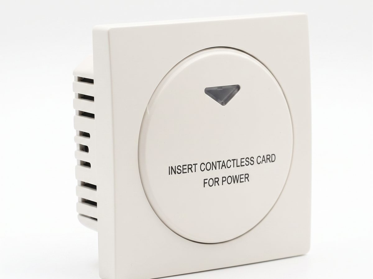
Interruptor de Tarjeta Hotel — Control Energía Habitación
Interruptor tarjeta hotel para control energía habitación. Detección RFID/IC, inserción-encendido, apagado retardado al retirar tarjeta. 220V CA, 10A-16A, RS485 o contacto seco. CE RoHS. Proveedor OEM/ODM.
Esta página ya lo señala como la siguiente referencia recomendada.
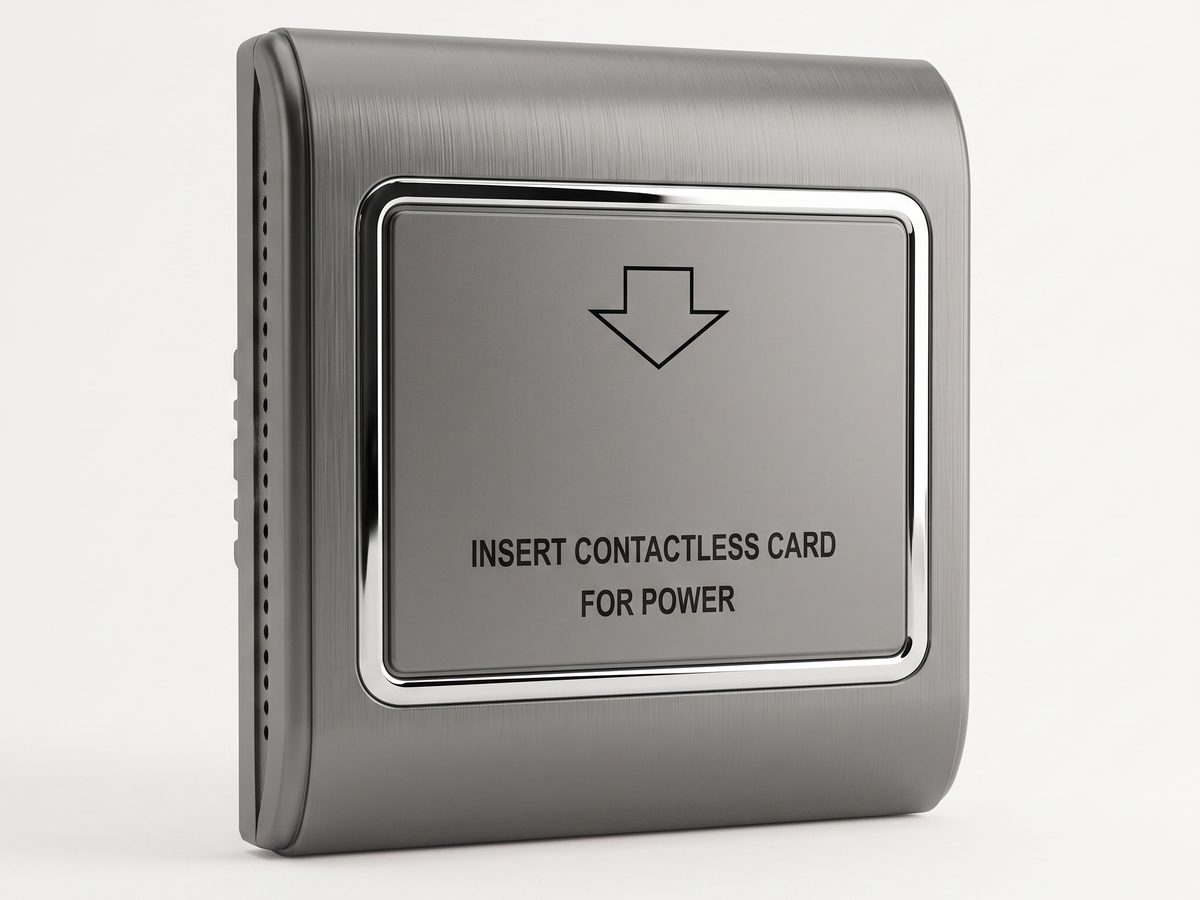
Interruptor RFID Ahorro Energía — Tarjeta MIFARE Vinculada Habitación (Tipo B)
Interruptor RFID ahorro energía vincula electricidad a tarjeta MIFARE habitación específica. 13.56MHz MIFARE / 125kHz Temic, CA 180–250V, 30A, 15s apagado retardado. Interruptor hotel RFID evita compartir tarjetas entre habitaciones y reduce 25–40% energía habitación.
Esta página ya lo señala como la siguiente referencia recomendada.
Interruptor TTLOCK Compatible — ID Habitación + Límite Tiempo (Tipo C)
Interruptor TTLOCK compatible con ID habitación y límite tiempo. Funciona con tarjetas MIFARE TTLOCK/TTHotel vía auth sector-clave, AC 180–250V, 30A. Interruptor tarjeta encriptado y TTLOCK ES2 para retrofits hoteles bloqueados ecosistema.
Esta página ya lo señala como la siguiente referencia recomendada.
Soluciones relacionadas
3 Guía de compra de interruptores de ahorro energético para hoteles 2026
Guía de compra de interruptores de ahorro energético para hoteles que cubre interruptores universales, RFID/MIFARE, compatibles con TTLOCK, BLE inteligentes y de sensor de ocupación. Elija el interruptor de energía por tarjeta, interruptor de inserción de tarjeta e interruptor de llave de ahorro energético adecuados para sus habitaciones.
Esta página ya lo señala como la siguiente referencia recomendada.
Sistema de gestión energética hotelera — Control de energía en habitaciones que se amortiza
Un sistema de gestión energética hotelera basado en interruptores de tarjeta, ahorradores RFID y sensores de ocupación que reduce un 25-40 % la electricidad en habitaciones. Guía de controlador energético para hoteles que renuevan la energía en habitaciones.
Esta página ya lo señala como la siguiente referencia recomendada.
Sistema de Gestión de Habitaciones con Control por Tarjeta
Un sistema práctico de gestión de habitaciones para controlar la energía mediante interruptores de tarjeta, contactores y reglas operativas documentadas.
Respaldan el mismo contexto de producto: Interruptor de Tarjeta Hotel — Control Energía Habitación, Interruptor RFID Ahorro Energía — Tarjeta MIFARE Vinculada Habitación (Tipo B).
Artículos del blog relacionados
3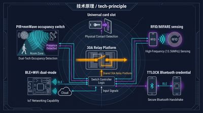
Interruptor de Tarjeta Hotel: Tipos, Modelos y Especificación
El interruptor de tarjeta para hotel incluye modelos universal, RFID, TTLOCK, BLE y ocupación. Guía sobre tipos, keycard switch y cómo especificar.
Respaldan el mismo contexto de producto: Interruptor de Tarjeta Hotel — Control Energía Habitación, Interruptor RFID Ahorro Energía — Tarjeta MIFARE Vinculada Habitación (Tipo B), Interruptor TTLOCK Compatible — ID Habitación + Límite Tiempo (Tipo C).

RFID vs NFC en interruptores de tarjeta llave de hotel: Qué elegir
RFID vs NFC en interruptores de tarjeta llave: alcance y bloqueo. RFID 125kHz/13.56MHz (MIFARE, Temic) es el estándar hotelero para energía en habitación…
Respaldan el mismo contexto de producto: Interruptor RFID Ahorro Energía — Tarjeta MIFARE Vinculada Habitación (Tipo B), Interruptor de Tarjeta Hotel — Control Energía Habitación, Interruptor TTLOCK Compatible — ID Habitación + Límite Tiempo (Tipo C).
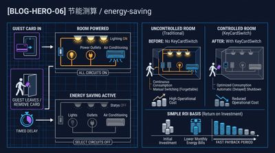
Interruptor de tarjeta llave de hotel: qué es y ahorro de energía
Un interruptor de tarjeta llave de hotel enciende la habitación al insertar la tarjeta y apaga al sacarla, ahorrando típicamente un 25-40% de electricidad.
Respaldan el mismo contexto de producto: Interruptor de Tarjeta Hotel — Control Energía Habitación, Interruptor RFID Ahorro Energía — Tarjeta MIFARE Vinculada Habitación (Tipo B), Interruptor TTLOCK Compatible — ID Habitación + Límite Tiempo (Tipo C).
Especifica tu proyecto hotelero con nuestros ingenieros
Envíanos el número de habitaciones, tipo de techo y preferencia de protocolo. Devolveremos un plan de muestra y cotización en 24 horas laborables.
- Pase de la guía general a una discusión de producto o aplicación.
- Use RFQ cuando precio, planos, MOQ o calendario de lanzamiento necesiten estructura.
- Mantenga visible una ruta de contacto directo para aclaraciones rápidas y traspasos.