Hotel Key Card Switch Wiring Diagram: Reading the Room Circuit
Hotel key card switch wiring diagram guidance for line-in, relay coils, contactors, terminals, load paths, and safe 180-250V guest-room installation.
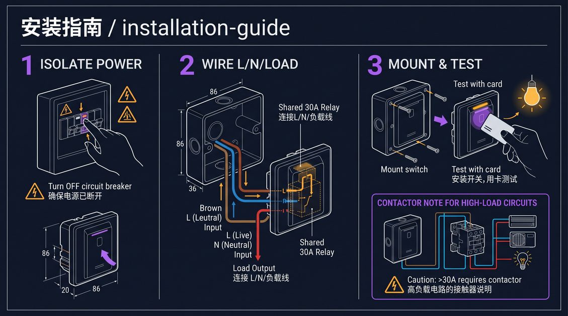
A hotel key card switch wiring diagram is the schematic that traces how the key card switch connects the guest-room live feed to a load-controlling relay or contactor, showing the line-in terminal, the coil drive pair, and the switching contacts that carry the room current. A component drawing or installed-wiring schematic of this kind maps every terminal: L for live-in, the reader supply points, the relay coil, and the common plus normally-open contact set that opens and closes the guest-room power path. Reading a hotel key card switch wiring diagram correctly tells an installer which cable lands on which terminal, which wire is low-current versus high-current, and whether the model relies on a built-in relay or an external contactor for a 180-250V alternating current room circuit. This guide explains each line, terminal, and protective device with worked examples, generic electrical safety steps, and the tray-side drawings used on site so an engineer can trace a fault, retrofit a panel, or size a board with confidence.
Hotel Key Card Switch Wiring Diagram: The Three Core Paths
A hotel key card switch wiring diagram can be reduced to three core paths that every installer must identify before touching a terminal: the line-in feed, the low-voltage coil drive, and the high-current switching path that actually powers the room. The line-in feed is the permanently live conductor brought from the room's distribution point to the switch, usually marked L or Line and rated for the switch's input range of AC 180-250V (110V variants available on request). The coil drive pair is the low-current loop that closes the relay or contactor when a valid card is inserted; it carries only the magnetizing current of the coil, typically a few hundred milliamps, so an installer can run it with thin cable all the way to the panel. The third path, the switching contacts, is the power-circuit pair that sits in series with the guest-room loads, carrying the full current of lights, sockets, and air conditioning.
Reading a hotel key card switch wiring diagram in this three-path mental model prevents two of the most common installation errors. The first error is treating the panel as a load-carrying device; a panel rated for the input voltage is not necessarily rated for 30A of switched load, and the diagram always shows whether the contacts are internal to the switch or delegated to an external relay or contactor. The second error is routing the high-current feed through the control pair, which either melts thin wiring or held the relay coil permanently energized. By separating the coil drive from the switching path on paper, the diagram makes the physical separation obvious, and the installer sizes two different cable gauges: a fine control pair for the coil and a heavier gauge for the contacts.
A useful habit when studying a hotel key card switch wiring diagram is to trace each path with a different color on a printout, confirming that the live feed arrives at the switch, the coil energizes in the return loop, and the common-to-normally-open contacts close into the room load. This trace also exposes the neutral requirements. Many flush key card switch designs need no neutral at the switch for basic operation, because the reader and coil draw from the line side and the return path is handled at the distribution board; a diagram that requires a neutral will show an explicit N terminal, and the installer must confirm one exists in the box before committing to the layout. Checking for an N terminal is one of the first verifications to make against the actual unit, because nothing on an installed wiring diagram can substitute for the label printed on the device.
| Circuit path | Terminals | Function | Cable gauge |
|---|---|---|---|
| Line-in feed | L (Line) | Powers reader and coil | Input-rated |
| Coil drive | Coil + / Coil - | Energizes relay/contactor | Thin control pair |
| Switching path | Common, N/O | Carries guest-room load | Load-rated |
Hotel Key Card Switch Wiring Diagram: Built-In Relay vs External Contactor
A hotel key card switch wiring diagram takes one of two broad shapes depending on whether the switching element is a built-in relay or an external contactor, and the two drawings are read differently because the current rating and mounting differ sharply. A built-in relay diagram is compact: the switch shows the line-in, an internal coil, and internal contacts all within one symbol block, and the installer simply wires line-in and the load out. A diagram that calls for an external contactor is divided into two boxes, one for the low-voltage coil side and one for the power side, with the installer running a control pair between them. Most flush key card switch models ship with an internal 30A relay, which covers the majority of single guest rooms; larger suites with upgraded HVAC or multiple high-amp appliances may exceed that rating and move to an external contactor.
Reading which shape applies matters because it changes where the high-current wire physically goes. On a built-in-relay hotel key card switch wiring diagram, the switched hot leaves the panel directly and fans out to the room loads; the panel itself carries the 30A current, so panel ventilation and the relay rating become the limiting factors. On an external-contactor diagram, the panel only receives the line-in and sends out a low-voltage control pair to the contactor's A1 and A2 coil terminals; the contactor, mounted at the distribution board or in a secure enclosure, carries the current through its own power terminals rated for the full load. The practical benefit is that the flush panel stays cool and the high-amp hardware is consolidated where the electrician can service it.
The decision between an internal relay and an external contactor is made at specification time, and the wiring diagram follows the decision. A property standardizing on the internal 30A relay keeps installation simplest and the panel count low, because there is no separate enclosure, no additional coil wiring, and no separate power terminal to label. A property with suites, ballrooms, or rooms that share one distribution board may already use a contactor for load balancing and prefer the external-contact drawing so the key card switch acts as nothing more than a smart coil trigger. Both are valid hotel key card switch wiring diagram families; the installer should confirm the intended current rating before ordering, because retrofitting an external contactor after an internal-relay layout is already pulled is needless rework.
Hotel Key Card Switch Wiring Diagram: Terminal-by-Terminal Reading
A thorough reading of a hotel key card switch wiring diagram walks the terminal label list one by one, because each label tells the installer what voltage and current belong there. The line-in terminal, labeled L or Line, receives the permanently live feed and must never be connected to an already-switched or load-side conductor. The neutral terminal, when present and labeled N, receives the neutral for the reader supply and must be confirmed present in the back box; if the diagram has no N terminal, the unit is designed to draw its return from the line side and needs no neutral at the switch. The coil terminals, often labeled Coil + and Coil - or A1 and A2 on an external contactor drawing, form the low-current loop that energizes the switching element when a card is inserted.
The switching terminals on a hotel key card switch wiring diagram are the common (C or COM) and the normally-open (N/O) contact, and these are the two terminals that sit in series with the room's live leg. When the card is inserted, the coil pulls in and the common-to-normally-open pair closes, handing live onward to the room load. A diagram may also show a normally-closed (N/C) contact, which is used for auxiliary signaling rather than for normal room power; the installer should not confuse N/C with N/O, because wiring the load to the wrong contact reverses the logic and could leave a room powered with no card. Color-coding on the diagram, where provided, marks the live feed brown or red, the neutral blue or black, the coil pair a thin control color, and the switching path the heaviest gauge.
A silent but important terminal on many hotel key card switch wiring diagram sheets is the earth or ground terminal, labeled E or PE, or represented by the standard earth symbol. Where the unit's metalwork is accessible and the local code requires bonding, the installer connects the earth conductor to provide the low-impedance fault path that lets a protective device clear a fault. Skipping the earth terminal on a metal-bodied unit is an electrical-safety error the diagram is specifically there to prevent, and the labeled E terminal is the sheet's way of forcing that connection. Before any power-up, the installer checks the earth continuity with a meter, verifying low resistance between the earth terminal and the panel ground path, as a first-pass safety gate.
Hotel Key Card Switch Wiring Diagram: The 15-Second Delay-Off Circuit
A central detail on any hotel key card switch wiring diagram is the delay-off behavior, the timing circuit that keeps the room powered for a short window after the card leaves the slot and then drops the contactor or relay. On paper, the delay shows up as a timing block between the card-present signal and the coil release; in practice it is a ~15-second hold that gives a guest enough time to swipe a second card or grab an item before the circuit opens. Reading this part of the hotel key card switch wiring diagram matters because it confirms that the load path is not cut the instant the card leaves, which would be harsh on compressors and electronics, but after the timed hold. The delay also gives housekeeping a predictable window during turnover.
The delay-off logic is part of the switch's internal control rather than something the installer wires, so the wiring diagram treats it as a single functional block labeled Delay 15s or similar. The installer's job is to connect the line feed, the coil drive, and the load path so that this internal timing can act on the coil; if the installer instead wired the load directly to a card-position switch, there would be no timer in the circuit and the room would drop instantly. The diagram signals this by showing the load controlled through the relay contact, never through a dry card reader output. An installer who respects that one relationship preserves the delay-off behavior without touching the control electronics.
For properties that prefer a shorter or longer hold, some models expose a small selector or trimmer, and the hotel key card switch wiring diagram marks it with a label such as Delay Adjust near the control block. Adjusting it is a settings change, not a rewiring task, and the diagram distinguishes the two so service staff do not open the high-current side to tweak timing. The practical reading is that the delay-off circuit is an integral function: verify the load path follows the relay, confirm the timing block exists, and leave the adjustment to the designated window on the device. A correctly read diagram delivers the predictable power-down that guests and housekeeping both rely on.
Hotel Key Card Switch Wiring Diagram: Step-by-Step Panel Installation
Following a hotel key card switch wiring diagram step by step turns a bundle of conductors into a working circuit when the installer works sequentially from the distribution side toward the panel. The first step is to isolate the supply at the distribution board, lock out the breaker, and verify zero voltage at the box with a meter; no wiring step happens while the circuit is live, because the diagram assumes the installer is working cold. The second step is to land the live feed on the line-in terminal and the coil drive pair on the coil terminals, using a control gauge sized to the drawing. The third step is to connect the switching path: the common terminal loops to the feed, and the normally-open contact runs onward to the guest-room loads, with a heavier cable gauge matching the load current.
With the conductors landed, the installer returns to the hotel key card switch wiring diagram to confirm each labeled terminal matches the physical label, then seats the flush 86x86mm panel into the single-gang box and secures it. The directive to seat the panel 29mm in the wall keeps the face flush with the corridor plaster and the wiring loop tidy behind the plate. After the mechanical fix, the installer re-energizes the circuit, inserts a valid card, and observes the coil close and the room loads energize within about one second. Removing the card should hold power for the 15-second delay and then open the circuit. Every step maps to a labeled terminal on the drawing, so a failed observation points to the one conductor that is wrong.
The same step sequence applies whether the drawing shows a built-in relay or an external contactor, with one difference in the middle. On an external-contactor hotel key card switch wiring diagram, the installer runs the coil pair out to the contactor enclosure, lands the pair on A1 and A2, connects the room feed through the contactor power terminals, and then proceeds with the panel mount. On a built-in-relay drawing, the coil is already internal and the installer skips the enclosure visit. Keeping the sequence identical reinforces a repeatable method, and a job card with the diagram printed at the operative start is a simple way to enforce it room after room across a retrofit program.
Hotel Key Card Switch Wiring Diagram: Common Faults and How to Read Them
The practical value of a hotel key card switch wiring diagram shows when a room fails to power on or fails to power down, because each symptom maps to a specific part of the drawing. A room that stays dead even with a card inserted most often traces to the coil drive loop: a loose coil terminal, a broken control conductor, or a lamp holder that never energized the coil. A room that powers on but will not switch off points to the load path or the coil removal logic: a short against the common-to-normally-open contact that keeps the circuit made, or a wiring error that routed the load through the N/C terminal, holding power opposite to the card state. Reading the diagram tells the technician which terminal to test first.
Voltage checks follow the paths of the hotel key card switch wiring diagram in a fixed order. The technician measures line-in to confirm the feed is present, measures across the coil terminals to confirm the coil is being commanded, and measures across the common-to-normally-open contacts to confirm the load path is being made and broken. A feed present with no coil voltage indicates the switch has not been satisfied by a valid card, moving the diagnosis to the card reader communication. A coil voltage present with no load output indicates the contact set itself, pointing to a pitted or welded contact or a blown wire. Each measurement narrows the field by the structure of the drawing, so the diagram is as useful for fault-finding as for first install.
Preventing recurring faults is a matter of torque and cleanliness, both visible on the hotel key card switch wiring diagram reviews. Every terminal screw should be torqued to the value printed beside it, because a loose coil terminal on a control loop produces intermittent behavior that is hard to trace and easy to misread as a reader fault. Contacts should be inspected during planned maintenance, because a contactor or relay that opens and closes thousands of times a season can pit its faces, and a pitted contact shows as an intermittent drop in the very rooms that cycle most. The discipline of reading the diagram during every service keeps the high-current path honest and reduces unplanned callouts.
| Symptom | Likely path | First test |
|---|---|---|
| No power with card | Coil drive loop | Coil voltage |
| No power at all | Line-in feed | L to neutral |
| Won't switch off | N/C wiring error | Contact position |
| Intermittent drops | Pitted contact | Contact resistance |
Hotel Key Card Switch Wiring Diagram: Generic Electrical Safety in the Circuit
The hotel key card switch wiring diagram is also an electrical-safety document, because it marks the isolation point, the earth path, and the load boundaries that keep a service technician safe. The isolation point is the breaker or protector feeding the room circuit; the diagram notes where to open it, and the standing rule is to work only with the supply isolated, locked, and verified dead. The earth path on the drawing, where an E terminal is shown, provides the low-impedance fault route that lets a protective device clear a fault rather than leaving a live metal surface; the installer must not omit it. These are generic electrical-safety principles, not specific to any code, and they apply to any 180-250V alternating current circuit a hand touches.
Lockout-tagout is the enforcement layer that turns the drawing's isolation point into a hard rule. Before opening the panel or the contactor enclosure, the technician isolates the circuit, applies a lock to the device, and verifies zero voltage with an appropriate meter. The hotel key card switch wiring diagram is printed beside the lock as the reference, so the person servicing the room knows exactly which breaker feeds which panel and which conductor must be tested. This sequence prevents the most dangerous scenario in room retrofit work: energizing a partially wired circuit because someone assumed the feed was dead. A diagram that marks the isolation point makes that assumption impossible to miss.
Fault protection on the drawing is stated in terms of a protective device sized to the load path, because the relay or contactor only routes current and does not itself protect against overload. Where the guest-room load could exceed the switching element, the diagram shows a supplementary protector between the feed and the switching path, sized to the conductor and the load. The technician checks the rating marks this protector against the machine's guidance and confirms it protects the smallest conductor in the path, because that conductor is the weakest point. By reading the protective boundaries rather than only the signal cores, the installer turns the paper schematic into a live, safe, serviceable circuit.
Hotel Key Card Switch Wiring Diagram: Planning a Multi-Room Retrofit
On a larger scale, a single hotel key card switch wiring diagram scales into a room-plan drawing that standardizes every circuit in a retrofit program, which keeps installation consistent and service records simple. The per-room drawing defines the feeder from the distribution board, the panel position at the entrance, the relay or contactor location, and the fan-out to lights, sockets, and air conditioning. A shared master diagram with a per-room label sheet lets an electrician wire a whole floor with the same terminal pattern, then note any room-specific deviation, such as a suite with extra HVAC, in the margin. Standardization is what makes a hundreds-of-rooms retrofit predictable on time and cost.
Reading the plan takes the same three-path model up a level. The line-in feeds cross the drawing room by room from the common board; the coil drive pairs are the thin control runs; the switching paths fan out as the load circuits. A hotel key card switch wiring diagram at plan scale highlights the shared infrastructure, which is where cross-room faults hide: a loose connection in a shared feeder or a mislabeled coil pair can take down several rooms at once. The plan makes shared points explicit, so the installer double-checks the common distribution side before resorting to chasing a fault room by room. Tagging every panel and contactor back to the plan keeps the whole retrofit auditable.
The plan also sets the safety and maintenance baseline by standardizing the lockout point and the earth path across the floor. Every room gets the same labeled breaker, the same earth connection where applicable, and the same protective device guidance, so a maintenance technician carrying the plan can walk any room and know exactly what to isolate. Because the room plan is derived from the single hotel key card switch wiring diagram, deviations are visible as exceptions rather than buried in per-room improvisation. Properties that standardize this way convert their key card power retrofit from a one-off installation into a managed, repeatable infrastructure that is easy to extend room by room or across buildings.
Hotel Key Card Switch Wiring Diagram: Checking Your Work Before Power-Up
Every hotel key card switch wiring diagram install should end with a staged verification, because a fault found during testing is far cheaper than a fault found on a guest's first night. The verification starts with a visual continuity check against the drawing, confirming the line-in lands on L, the coil pair lands on the coil terminals, and the load path runs through common-to-normally-open. The installer then checks that no conductor bridges two terminals and that the earth, where present, has low continuity to the ground path. Finally, the installer confirms the correct gauge was used for the switching path, because the high-current core is the one that must not be undersized. These three checks cover the drawing's three paths.
The power-on test follows the staged order the diagram implies. With a test lamp fitted rather than the guest-room load, the installer energizes the circuit, inserts a card, and confirms the coil closes and the lamp lights. Removing the card should hold the lamp for the 15-second delay and then extinguish it, proving the delay-off block works in the real installation. A final check re-verifies the lockout point by opening the room's breaker and confirming the panel and load drop cleanly. Each success confirms one relationship on the hotel key card switch wiring diagram, and any failure identifies the single conductor to re-examine. A room that passes this sequence is ready for a real guest.
The last discipline is documentation, because a hotel key card switch wiring diagram is most valuable when it is bound to the physical install. The installer labels the panel, the contactor or relay, and the protective device with the room number, and files the marking drawing back into the maintenance record with any deviation noted. When the next technician arrives, the filed diagram is the first reference, and the labels let them walk the physical circuit with confidence. This habit converts a one-time retrofit drawing into a living maintenance asset, keeps a multi-room program coherent, and ensures that every subsequent service or extension starts from an accurate picture of the room. The wiring truly begins and ends with the diagram.
Hotel Key Card Switch Wiring Diagram: Reading the Drawing Legend
The very first thing to master on a hotel key card switch wiring diagram is its own legend, because the symbols at the bottom of the sheet are the grammar that makes every terminal readable. A legend typically lists the line symbol (a solid line for the live feed), the control pair (often a thinner or dashed line for the coil loop), and the load path (the heaviest line on the sheet), along with the marks for a normally-open contact, a normally-closed contact, and a coil. A relay symbol on a wiring sheet is drawn as a coil with a parallel blade for the contact, and the installer reads across the sheet to connect the coil on one side to the contact it drives on the other. Without translating the legend, two installers can look at the same page and argue about which blade is common, which is the mistake that produces reversed switching.
Reading the legend also resolves the dozens of small marks that otherwise look like decoration: a dot at a junction means conductors are connected, a break with no dot means they cross without touching, and a small label letter such as A1 or A2 is the physical terminal name printed on the device. A lightning or appliance symbol marks the load; an arc-between-blades mark indicates a contactor, which is a magnetically held power switch used when a room draws more current than a small relay can carry. On a multi-room hotel key card switch wiring diagram the legend further defines the feeder bus, the room branches, and the shared protective device, so a maintenance electrician reading one sheet can find the specific branch that feeds a specific guest room. Learning the legend once makes every subsequent page read at a glance rather than by guesswork.
The legend also teaches the installer which statements on the sheet are physical constraints and which are advisory. A rated value printed beside a contact, such as the 30A AC rating, is a hard boundary that must not be exceeded because the contact gap and material are sized for it. A shading or a note about cable gauge farther down the sheet is advisory guidance about component specification and is adjusted only with engineering approval. Distinguishing these two classes on the hotel key card switch wiring diagram prevents two failure modes: overloading a contact beyond its rating, and treating a sizing note as iron law when a room deviates. When the reading feels ambiguous, the label printed on the actual device is the source of truth, and the legend is the second opinion to cross-check against it.
Hotel Key Card Switch Wiring Diagram: Sizing Cable and Protective Devices
A hotel key card switch wiring diagram is only as good as the cable and protective device sizes it implies, because the drawing shows topology while the rated values carry the physical duty. The control pair that energizes the coil carries only magnetizing current, a few hundred milliamps, so a thin gauge is electrically sufficient; the real constraint here is mechanical durability along a run through the panel cavity. The switching path, by contrast, carries the full guest-room load, so its gauge must satisfy the current drawn by lights, sockets, and air conditioning together, with derating for conduit fill and ambient temperature. The diagram or its attached schedule names both, and the installer sizes the two cores differently, which is why they are always drawn with different line weights. Undersizing the switching path is the most common thermal defect found late, when a warm cable is discovered behind a plate after weeks of guest use.
The protective device is sized to protect the conductor, not the load, and the hotel key card switch wiring diagram marks its location at the head of the room circuit. A rating is chosen so a fault or overload on the room route clears before the cable heats to a damaging temperature, while still allowing normal inrush from the air conditioning compressor. The installer matches the protective device rating marks to the smallest conductor in the circuit, because protection is only as strong as the weakest link. Where a control transformer or a separate coil supply exists, the sheet shows that branch protected individually, so a fault in the low-voltage side does not trip the house power to the whole room. Together, the gauge schedule and the protective device rating turn the diagram into a complete specification that a purchasing team can order against and an electrician can install without reverse-engineering the load.
Good practice is to record the chosen gauge and protector rating directly on the marked-up hotel key card switch wiring diagram stored with the room, because the drawing then serves as the as-built record. A schedule table in the sheet columns—room, feeder gauge, control gauge, protector, relay or contactor—lets a property confirm at a glance that no room deviates from the standard without an approved note. When a suite is later upgraded to a larger air conditioning unit, the installer recalculates the switching-path gauge against the new load and updates the schedule, keeping the as-built record true. This discipline turns the initial drawing from a design aid into the single source of truth for every subsequent wiring decision on the property.
Hotel Key Card Switch Wiring Diagram: Multi-Room Board and Distribution Planning
Moving from one room to a floor, a hotel key card switch wiring diagram generalizes into a distribution plan where every guest-room circuit hangs off one common board, and the way the feeder is bused decides how a fault affects neighbors. Each room gets its own branch from the shared feeder, its own protective device, and its own panel and relay or contactor, so a single-room fault clears in that room without killing the floor. The common board carries the incoming supply, distributes it room by room, and houses the shared protective device; the contacts of every room's switch or contactor refer back to this board because the coil return and the load feed both terminate around it. Reading the board-side portion of the hotel key card switch wiring diagram tells the installer where a room begins, so a mislabeled feeder cannot silently join two rooms together.
The distribution logic that appears on the plan is a star, not a chain. A star feeds each room from the board independently, so the rooms are electrically isolated from one another and a fault in room ten does not drop room eleven. A chain that loops one room into the next is cheaper to pull but couples every downstream room to the health of the link before it, a design a well-drawn plan avoids. When an existing property already has cham-room runs laid out as a chain, the retrofit plan notes each link so the installer knows which room is the point of failure and can decide whether a board-side tap is worth the work. The hotel key card switch wiring diagram at floor scale makes the topology explicit, and the installer can weigh cost against isolation before the cable is pulled.
The plan also standardizes the earth and grounding strategy across the floor, because several rooms sharing one conduit can composite earth paths into a noisy or unsafe common point. Each room's earth, where applicable, is run back and terminated at the board's earth bar, and the plan marks that bar so every room ties to the same reference. This consistency keeps the fault path well defined and lets a technician verify earth continuity with a single meter reading at the board rather than per room. A floor planned around one cohesive hotel key card switch wiring diagram therefore yields a distribution board that is easy to isolate, easy to extend, and easy to audit, which is exactly what a property needs when a retrofit grows over successive seasons.
Hotel Key Card Switch Wiring Diagram: Commissioning and Load Testing the Circuit
Commissioning is the stage where a hotel key card switch wiring diagram gets proven against reality, running from a cold check through a live load test before any guest rests in the room. The cold check compares the installed conductors to the drawing with the supply isolated: continuity across each named terminal, no accidental bridge between adjacent points, and a clean earth path where one is required. A multimeter in resistance mode walks the three paths from the sheet, confirming line-in reaches the correct point, the coil pair is not shorted to the switching contact, and the load path runs unimpeded to the room fan-out. Any continuity that does not match the diagram is caught here, where it costs minutes to correct rather than a night of trouble. The cold phase is deliberately dull and thorough, because that is where wiring mistakes are cheapest.
The live test then follows the exact order the diagram implies, always starting with a dummy lamp rather than the actual room equipment. The installer energizes the circuit, inserts a card, and confirms the relay or contactor pulls in and the test lamp lights within about a second; removing the card should hold the lamp for the 15-second delay and then drop it. This proves the delay-off block, the coil loop, and the switching path all work in the real assembly. Only after the sequence passes on a lamp is the room load connected and re-tested, because an error on a compressor or a bank of fixtures is more costly and harder to isolate than an error on a lamp. Load testing also catches weld or contact temperature under real current, which a lamp test cannot, so the loaded run is the true final proof.
The commissioning record matters as much as the electrical test, because a hotel key card switch wiring diagram becomes the maintenance baseline once it is stamped as the as-built. The installer dates the sheet, notes the gauge and protector used, marks any deviation approved during installation, and files it beside the label on the panel. A subsequent technician armed with that record can walk the physical circuit against the drawing in minutes, confirm nothing drifted, and extend it with confidence. The commissioning stage closes the loop that begins with reading the legend and ends with a documented, tested, safe circuit, and it is the step that turns a drawing into a durable asset for the life of the room.
Part of this article content is generated by AI and optimized for professional accuracy and readability.
Not sure which sensor fits your project?
Talk to our mmWave application engineers for a free consultation.
Find the right presence sensor for your hotel project
Compare the 3 protocols, check hotel-specific case studies, and download the installation guide
Related products
3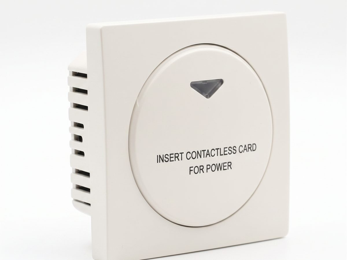
Hotel Key Card Switch — Guest Room Power Control
Hotel key card switch for guest room power control. RFID/IC card detection, insert-and-power, card removal time-delay power-off. 220V AC, 10A-16A, RS485 or dry contact. CE RoHS. OEM/ODM supplier.
This page already points to it as the next recommended reference.
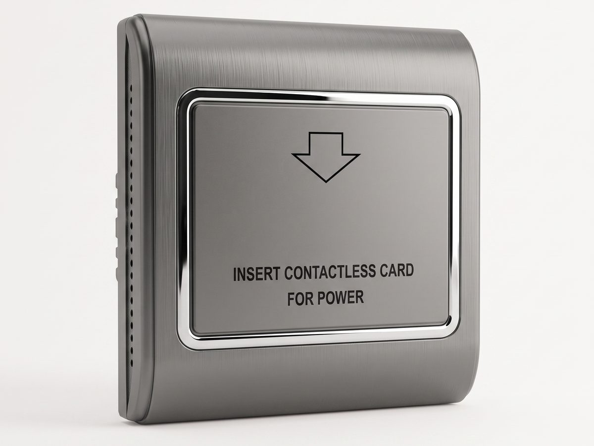
RFID Energy Saving Switch — Room-Bound MIFARE Card Switch (Type B)
RFID energy saving switch that binds power to a specific room MIFARE card. 13.56MHz MIFARE / 125kHz Temic, AC 180–250V, 30A, 15s delay-off. An RFID hotel switch that stops card-sharing between rooms and cuts 25–40% room energy.
This page already points to it as the next recommended reference.
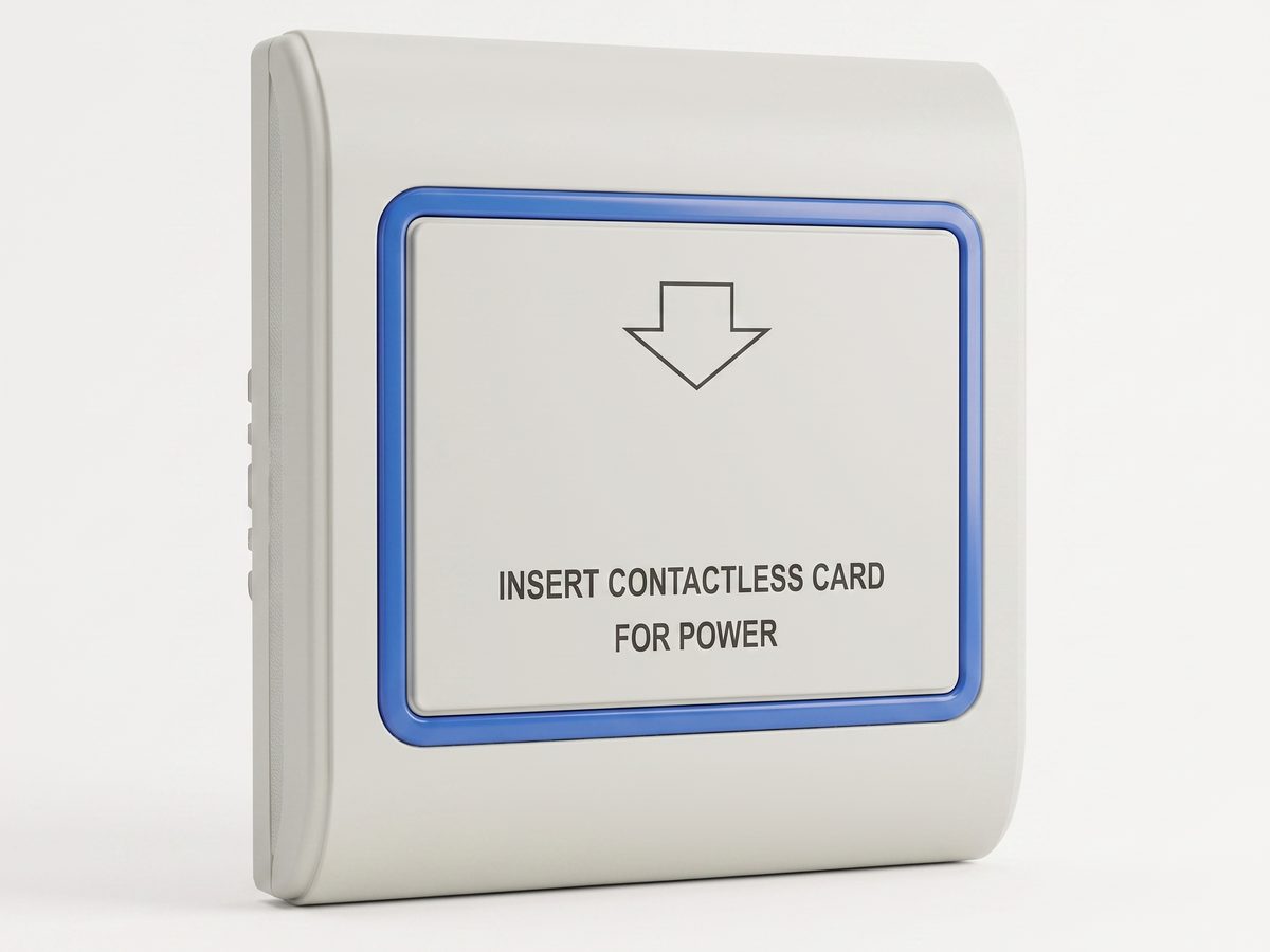
RFID Key Card Switch — Contactless 13.56MHz Guest Room Power Control
RFID key card switch with contactless 13.56MHz detection. Guest simply taps a card on the reader area to power the room, no insertion slot needed. Works alongside hotel door locks. CE RoHS. OEM/ODM supplier.
This page already points to it as the next recommended reference.
Related solutions
3Hotel Room Retrofit with Key Card Power Switches
A practical hotel room retrofit program for replacing outdated guest-room power controls with compatible key card switches and contactors.
This page already points to it as the next recommended reference.
Guest Room Management System Based on Card-Controlled Power
A practical guest-room management system for controlling room power through key card switches, contactors, and clearly documented operating rules.
It supports the same product context: Hotel Key Card Switch — Guest Room Power Control, RFID Energy Saving Switch — Room-Bound MIFARE Card Switch (Type B).
Hotel Energy Saving with Guest-Room Power Switching
A hotel energy-saving solution that uses card-controlled room power to prevent lights, air conditioning, and selected outlets from running unnecessarily.
It supports the same product context: Hotel Key Card Switch — Guest Room Power Control, RFID Energy Saving Switch — Room-Bound MIFARE Card Switch (Type B).
Related blog posts
3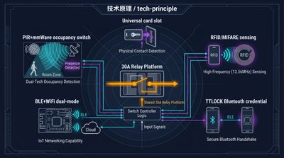
Hotel Key Card Switch: Types, Models, and How to Specify
A hotel key card switch spans universal, RFID, TTLOCK, BLE, and occupancy models. This guide to the key card / keycard switch family covers the head terms —…
It supports the same product context: Hotel Key Card Switch — Guest Room Power Control, RFID Energy Saving Switch — Room-Bound MIFARE Card Switch (Type B).

RFID vs NFC for Hotel Key Card Switches: Which Card Tech to Choose
RFID vs NFC for hotel key card switches comes down to range and lock-in: 125kHz / 13.56MHz RFID (MIFARE, Temic) is the hotel standard for room-bound power…
It supports the same product context: RFID Energy Saving Switch — Room-Bound MIFARE Card Switch (Type B), Hotel Key Card Switch — Guest Room Power Control.
What Is a Hotel Key Card Switch and How It Saves Room Energy
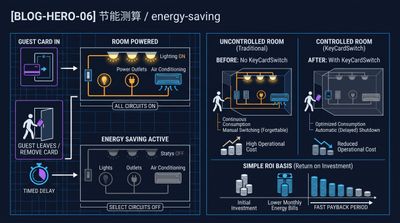
A hotel key card switch is a wall device that powers a guest room when a card is inserted and cuts it when removed, typically saving 25–40% of room…
It supports the same product context: Hotel Key Card Switch — Guest Room Power Control, RFID Energy Saving Switch — Room-Bound MIFARE Card Switch (Type B).
Specify your hotel project with our engineers
Send your room count, ceiling type, and protocol preference. We will return a sample plan and quote within 24 business hours.
- Move from general guidance into a product or application discussion.
- Use RFQ when pricing, drawings, MOQ, or launch timing needs structure.
- Keep a direct contact path visible for fast clarifications and handoff.