Hotel Key Card Switch Troubleshooting Guide: Diagnose and Fix Guest Room Card Reader Failures
A hotel key card switch troubleshooting guide for maintenance engineers covering common failures like no power, stuck-on LEDs, dead relays, and card read errors.
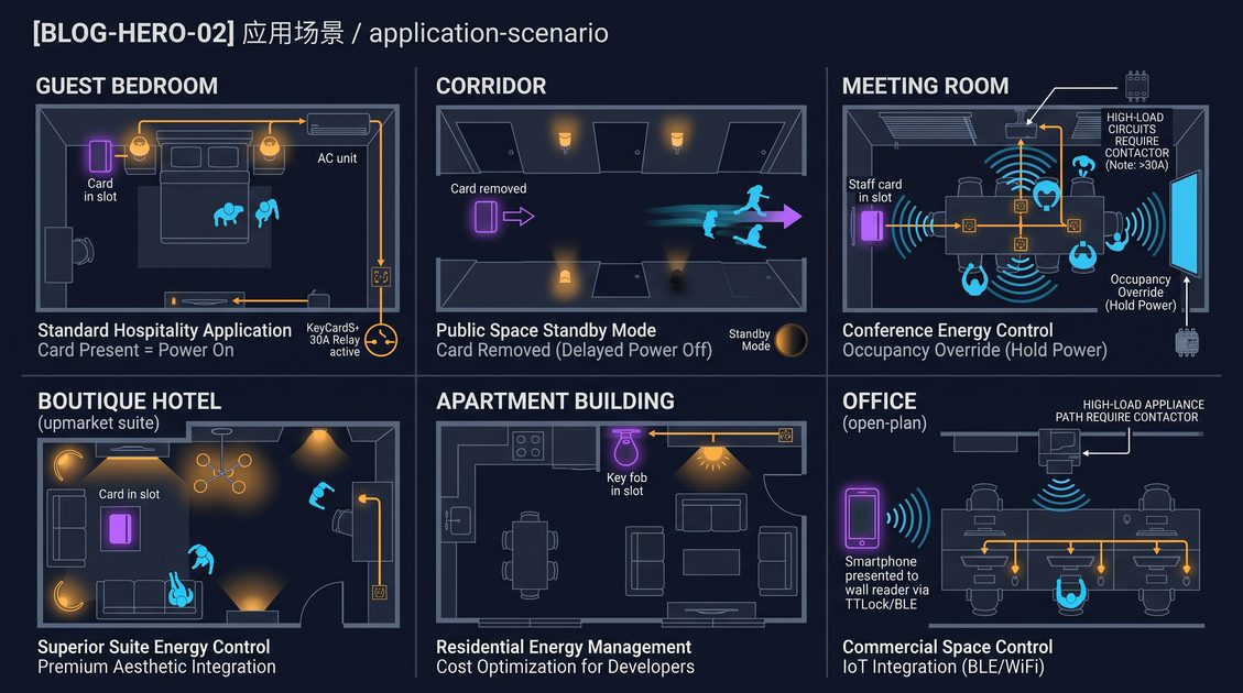
A hotel key card switch troubleshooting guide is a practical diagnostic reference for engineering and maintenance teams that service the card readers, relays, and load-control circuits that power guest room outlets, lighting, and air conditioning. When a guest inserts their card and nothing lights up, or the power never cuts off after checkout, the root cause can sit anywhere between the wall box, the card reader, the relay, and the connected load, so a structured checklist is far more effective than trial and error. This guide walks through the most common failure modes, a repeatable step-by-step test flow, the tools you need on the trolley, and clear decision rules for when a unit can be repaired in place versus when it should be swapped for a new switch. Electrical work on live circuits carries real risk, so every step here assumes that power is isolated and locked out before any terminal is touched.
Introduction to the Hotel Key Card Switch Troubleshooting Guide
A hotel key card switch is a load-control panel mounted at the room entrance that energizes guest room power only while a valid card is inserted and cancels it when the card is withdrawn. It is essentially three subsystems in one enclosure: a card-reading section that validates the credential, a logic or controller section that interprets the card state, and an electromechanical or solid-state switching section that connects the line to the load. Most residential-style card switches operate at 100 to 240 VAC input and switch a load of 8 to 16 amps, with a relay that remains closed while the card is present and opens after a delay of 10 to 90 seconds or more when the card is removed. This guide approaches failures the way a field engineer would, starting from observable symptoms, narrowing to a subsystem, and confirming the fix before the room is returned to service. Because the same physical unit can exhibit dozens of different behaviors, the material is organized by symptom first and by test procedure second, so that a maintenance team can jump straight to the section that matches the complaint on the work order.
How a Working Unit Behaves Before You Test Anything
Before you start the hotel key card switch troubleshooting guide, it helps to recall the expected behavior of a healthy unit so abnormal readings stand out. Insert a valid card front and center into the slot. The reader should confirm the card, usually with an indicator LED that changes color, and the relay should energize within about 0.5 to 1 second, switching line power to the outlets and fixtures. Remove the card and the relay should remain closed through the programmed delay-off interval, then open to drop the load. With the room unoccupied overnight, the switch should hold a low stand-by state that draws only a few milliwatts from the control supply. Any deviation from this sequence, whether it is a light that never turns on, a relay that clicks but stays open, or a load that keeps running after the card is gone, is the start of a diagnostic trail that the rest of this guide will help you trace.
The Four Subsystems You Are Really Testing
The entire hotel key card switch troubleshooting guide reduces to four components. First is the power input stage, the fuse, MOV, and voltage-regulating supply that turns line voltage into a safe DC rail for the logic. Second is the reading stage, an optical sensor for magnetic stripe cards or an RFID reader coil and antenna for contactless cards, which produces a signal only when a matching credential is present. Third is the control stage, usually a microcontroller or comparator that decides whether to energize the relay and how long to hold it after the card leaves. Fourth is the output stage, the relay contacts or TRIAC that actually carries load current. In practice, roughly half of all field-reported failures turn out to be the card, the wiring, or the load rather than the switch itself, which is why the diagnostic method here deliberately checks externals before it blames the unit.
Hotel Key Card Switch Troubleshooting Guide: Reading the Common Symptoms
The fastest way to work through any hotel key card switch troubleshooting guide is to start from the symptom a guest or housekeeper actually reports and map it to the most likely failing subsystem. Most complaints fall into seven patterns, and each one points at a different place to investigate. The table below summarizes the symptom, the usual cause, and the first place to look, and the sections that follow it give the detailed test for each row.
| Symptom | Most Likely Cause | First Check |
|---|---|---|
| Insert card, no indicator, no power | No input power or dead control supply | Measure line voltage at the input terminals |
| Insert card, indicator on, no output | Relay not energizing or load open | Verify relay continuity and the load circuit |
| Card has no effect, reading fails | Wrong card type, dirty reader, weak signal | Test with a known-good valid card |
| Power never cuts off after card removal | Welded or jammed relay contacts | Measure relay output after the delay window |
| Indicator light stays on constantly | Stuck control logic or shorted output | Remove card and watch the delay cycle |
| Delay is too short or too long | Mis-set DIP switch or dying timing capacitor | Check the delay configuration and bench test |
| No output at all, unit totally dead | Blown fuse, open trace, failed supply | Inspect fuse and input supply voltage |
Insert Card, No Indicator, No Output
This is the most common call, and it usually points at the power input stage rather than the reading stage. If the indicator LED does not come on at all when a known-good card is inserted, the control board has no supply rail, which means either the room breaker feeding the switch is tripped, the input wiring is loose or reversed, the internal fuse is open, or the on-board voltage regulator has failed. A quick voltage check with a multimeter at the line and neutral input terminals answers most of these in under a minute. If line voltage is present but the board still appears dead, you have isolated the problem to the internal power supply, which is a repair or replace decision rather than a wiring fix. Always confirm that the breaker that feeds the switch is actually supplying power before you open the wall box.
Insert Card, Indicator On, No Relay Output
If the indicator lights correctly but the load never comes on, the reading and control stages are probably healthy and the fault sits in the output stage or the load. The relay may be failing to energize, the relay contacts may be pitted and high in resistance, or the wiring from the relay output to the sockets and fixtures may be broken. You can separate these by measuring continuity across the relay output terminals while a card is inserted. If the output terminals become continuous but the room stays dark, the problem is downstream in the load wiring. If the output terminals stay open, the problem is the relay or the controller driving it.
Card Reading Fails or Ignores the Card
When the switch simply ignores an inserted card, the likely causes are a card of the wrong card type, a worn or dirty reader slot, a weak RFID signal, or a card that has not been properly encoded. For magnetic stripe cards, check that the stripe faces the correct direction and that the reader head is clean. For RFID cards, confirm the card uses the same frequency and encoding as the lock system the switch is paired with, such as 125 kHz EM or 13.56 MHz Mifare. A sure test is to insert the master or a known-good card from a neighboring room; if that works, the switch is fine and the guest card is the issue.
Power Never Cuts Off After Card Removal
A switch that keeps the power on after the card is removed points to a relay whose contacts are welded shut, a shorted switching device, or control logic stuck in the energized state. This symptom also creates an energy-waste and safety issue, because lights and air conditioning keep running with the room empty. After the delay window passes, measure continuity across the relay output. If it stays continuous with the card removed, the output device is stuck and the switch should be replaced, because a welded relay is not reliably repairable in the field.
Indicator Light Stays On Constantly
When the indicator never changes state, treat it as a control-logic symptom. The card may be stuck in the slot against the reader, the micro-switch may be mechanically bound, or the controller may be failing to detect the card leaving. Verify that the slot is physically free, remove the card, and give the delay window time to expire. If the light stays on regardless of card position, the reader micro-switch or the logic board is at fault.
Delay Too Short or Too Long After Card Removal
An abnormal delay-off interval is usually a configuration issue rather than a hard failure. Many switches expose a DIP switch or jumper block that sets the hold time from about 15 seconds to several minutes, and a mis-set switch produces a delay that does not match the property standard. If the delay is inconsistent or drifts over time with no config change, the timing capacitor on the logic board may be aging. Confirm the DIP switch position against the manual first, then bench-test repeatability before assuming component failure.
Hotel Key Card Switch Troubleshooting Guide: The Step-by-Step Diagnostic Flow
The core of any hotel key card switch troubleshooting guide is a repeatable sequence that isolates the fault without removing every component at once. The method below takes roughly ten to fifteen minutes per room when the tools are on hand, and it works the same way for magnetic, RFID, and hybrid switches because it tests power first, reading second, switching third, and timing last. Each step is designed so that a positive or negative result tells you exactly which subsystem to blame and what to do next. Always isolate the branch circuit at the panel and apply lockout/tagout before any terminal is touched, because exposed line voltage at the wall box is a shock hazard even when the room appears dark.
Step 1: Confirm Power and Input Integrity
Start at the input. With the circuit isolated, open the wall box, identify the line, neutral, and any earth conductor, and visually inspect the terminals for looseness, corrosion, or scorching. Reconnect, restore power, and measure 100 to 240 VAC across the input with the switch in circuit. A healthy reading here confirms the supply and wiring, so you can move to the reading and control stages. A missing reading means the problem is upstream in the breaker or feed, not in the switch.
Step 2: Verify the Card-Reading Stage
With input power confirmed, insert a known-good, correctly encoded card of the same type the room is supposed to accept. Watch the indicator and listen for the relay click. If the indicator changes but the relay does not click, the control stage is not pulsing the output, which points to the logic board. If neither the indicator nor the relay responds, the reading stage is not detecting the credential. Test the same card in a second, known-good switch to rule out a bad guest card before you condemn the unit.
Step 3: Test the Relay and Load Circuit
Hold a valid card in place and use continuity mode to confirm that the relay output terminals become closed. Then verify that voltage actually reaches the outlets or fixtures by measuring at the load. Three outcomes resolve the picture: output closed and load live means the switch is good and the original complaint was transient; output closed but load dead means the fault is in the room wiring or the fixture; output open means the relay or controller is at fault inside the switch.
Step 4: Check the Delay and Hold-On Timing
Remove the card and time how long the relay stays closed. Compare the measured hold time with the DIP switch or jumper setting. A gross mismatch points to misconfiguration, which you can correct by setting the switch to the property standard. A correct setting but clearly random or drifting hold time points to a failing timing component, which is a quality issue that favors replacement. Run the removal cycle at least three times to confirm the timing is consistent before you sign off.
Step 5: Bench-Test the Unit Off the Wall
If the in-wall tests leave doubt about whether the switch itself is good, remove it, take it to the bench, and test it with a card and a small test lamp or a 100-watt equivalent resistive load on a fused supply. A bench test removes the room wiring as a variable and gives a clean answer on read, relay, and delay in under five minutes. Mark the unit with the result so the team knows whether it is fit to return to stock or should be discarded.
Testing Tools That Support the Hotel Key Card Switch Troubleshooting Guide
A short tool list makes the entire hotel key card switch troubleshooting guide faster and safer, because very little can be diagnosed reliably by eye alone. The items below cover input power, relay continuity, live load, and card validity, and all of them fit in a standard engineer bag.
| Tool | What It Confirms | Typical Reading on a Healthy Unit |
|---|---|---|
| Digital multimeter | Input voltage, relay continuity, leakage | 100-240 VAC input; near-zero ohms when energized |
| Non-contact voltage tester | Presence of live voltage without contact | Lights when near an energized conductor |
| Continuity probe or tone | Relay contact closure | Tone/stability when relay is energized |
| Test card, encoded | Card reading and encoding match | Indicator changes and relay clicks |
| Test lamp or dummy load | Real load behavior | Lamp lights with card in, goes dark after delay |
| Spare switch or adapter | Isolation of switch versus wiring | Verifies the offending unit on the bench |
How the Multimeter Is Used in Each Step
The digital multimeter is the workhorse across the whole hotel key card switch troubleshooting guide. Use the AC voltage range to confirm the input supply, the continuity and low-ohms range to check relay contact closure, and the DC range to verify the control rail when available on the board header. Keep the probes on insulated inspection tips and set the meter to the correct range before connecting, because reading live voltage on a resistance range draws a short and can trip the supply. A meter with a backlit display and audible continuity is a genuine timesaver inside a dark wall cavity.
Why a Test Card Matters More Than It Seems
A surprising number of first-level fix attempts fail because the test credential is wrong. For the hotel key card switch troubleshooting guide to be reliable, you need at least one known-good card of the correct card type, correctly encoded, that you reserve for diagnostics and never hand to a guest. If that card stops working, you learn about the switch reading stage or the encoder, not the guest experience. Keep two test cards per maintenance trolley so a worn card does not produce a false pass.
Safety Tooling That Belongs in the Kit
Electrical diagnosis is only as safe as the isolation you perform before it. In addition to meters and cards, the kit should carry a lockout/tagout set for the branch panel, insulated screwdrivers, voltage-rated gloves for switchgear, and a proximity voltage tester as a redundant check. The rule is simple: verify dead with a rated meter and a non-contact tester before you open any box, and lock the breaker so someone else cannot restore power while your hands are inside. No troubleshooting step in this guide is worth a shock.
Detailed Diagnosis for Each Failure in the Hotel Key Card Switch Troubleshooting Guide
Where the earlier flow gives the sequence, this section goes symptom by symptom through the hotel key card switch troubleshooting guide and explains the likely physics and the exact readout that confirms each fault. Every symptom here begins with a short self-contained answer block, then breaks into the cause, the test, and the fix as separate pieces so an engineer can scan straight to the row that matches the work order. Reading these side by side also reveals how the subsystems recommend one diagnosis over another, because the same indicator states can often be produced by two different root causes that need opposite fixes.
Why a Failed Power Supply Produces a Completely Dead Switch
A completely dead switch, no indicator, no relay, no load, is almost always a power-input problem rather than a reading problem, because every other stage is starved without a DC supply rail. The probable causes in order are a tripped or failed branch breaker, a loose or reversed line and neutral pair at the terminals, an open internal fuse, or a failed voltage regulator on the control board. The confirming test is a multimeter across the input terminals; if you read the expected 100 to 240 VAC at the input but the board stays dark, the fault has moved inside the unit and the replace decision has already been made. If you read nothing at the input, open the panel and verify the breaker and the feeding conductor before you do anything else. Reconnect, restore and re-verify before closing the box.
Why a Weak Magnetic Stripe Produces an Intermittent Failure
An intermittent failure, one where the switch works on some inserts and not others, is the classic signature of a dirty or worn magnetic stripe and a reader head that reads it inconsistently. The magnetic stripe degrades with abrasion, exposure to magnets, and contact with the reader slot, so a guest card that sees heavy use reads poorly even though it is still encoded. In the hotel key card switch troubleshooting guide the correct test is to compare the suspect card against a known-good card of the same type in the same switch. If the good card reads reliably and the suspect card does not, you have confirmed a card-side fault and the answer is to encode a fresh card, not to replace the switch. Wipe the slot and the stripe clean, and re-test before you file the report.
Why an RFID Switch Ignores a Contactless Card
When an RFID hotel key card switch ignores a brand-new 125 kHz or 13.56 MHz card, the cause is most often a card that does not match the reader protocol, not a broken reader. Different lock systems encode cards on different frequencies and data formats, and a card from one system will not trigger a switch paired with another system even though both look identical. The confirming test is to pass the card under the switch and watch for any acknowledgment, then try a card known to come from the room's own system. If the correct card works, the switch is healthy and the guest card is simply from the wrong population. If no card of the correct type works, the reader coil or its driver on the board has failed and the unit should be replaced.
Why Welded Relay Contacts Hold Power On
A switch that keeps the room powered after the card is removed points to a relay whose contacts have welded shut under load or a TRIAC that has shorted. When the contact is welded, the mechanical link cannot break conduction even when the control coil is de-energized, so the load stays on indefinitely. The confirming test in the hotel key card switch troubleshooting guide is simple: remove the card, wait through the full delay window, and measure continuity across the relay output. If continuity persists with the card out, the output device is stuck, the fault is permanent, and the switch must be replaced. Do not attempt to exercise or tap the relay back into service, because a welded contact that momentarily opens is still damaged and can fail in the load path again.
Why a DIP Switch Setting Changes the Delay You Measure
A delay-off time that does not match the property standard is normally a configuration matter. Most card switches expose a DIP switch or jumper that selects the hold-on time from roughly 15 seconds up to a few minutes, and a switch set to the wrong position produces a delay that looks like a fault to a housekeeper. The confirming check is to compare the DIP switch position against the printed index on the unit and the manual, then set it to the property standard and run the removal cycle. If the delay then matches the standard and stays repeatable across three cycles, the unit is healthy and the configuration is the fix. Only when the delay drifts randomly with no config change should you suspect an aging timing capacitor and move to replacement.
Why Contact Corruption or Loose Terminals Mimic a Relay Failure
Sometimes the readout suggests a relay failure when the real problem is a loose or corroded load connection downstream. If the relay clicks and continuity is good at the output terminals but the room stays dark, the open is in the wiring between the switch and the fixtures, not in the switch. The confirming step is to chase voltage from the relay output to the first outlet and fixture with a multimeter, looking for the point where the live signal disappears. Re-tighten any loose terminal, repair any broken conductor, and re-test. This distinction matters because it saves a working switch from being discarded over a cabling fault, and it is a reminder to treat the wiring, not just the device, as part of the circuit under test.
FAQ: Common Questions in the Hotel Key Card Switch Troubleshooting Guide
| Question | Short Answer |
|---|---|
| Why does the switch ignore a card that works in another room? | Different switch or lock system encoding; use the room system card |
| Can I fix a relay that stays stuck on? | No, replace the unit, it is not safely field-repairable |
| Does a blown fuse always mean the switch is bad? | Not necessarily; check the breaker and any external fuse panel first |
| How long should the delay-off last? | Set the DIP switch to the property standard, usually 15 seconds to a few minutes |
| Do I need to replace the whole unit for a dirty reader? | No, clean the slot and stripe first, re-test, then decide |
Repair versus Replace in the Hotel Key Card Switch Troubleshooting Guide
Part of the hotel key card switch troubleshooting guide is knowing when a unit can be brought back to service and when it should be removed and replaced. In general, loose terminal screws, a blown external fuse at the panel, mis-set delay switches, and dirty card reader slots are repairable in place at no component cost. Internal failures such as a dead regulator, a failed timing capacitor, a cracked trace, or welded relay contacts are almost always more economical to replace than to repair, because labor alone can exceed the price of a new switch and a repaired unit typically carries no guarantee. The table below gives a practical decision matrix.
| Condition | Repair in Place | Replace | Notes |
|---|---|---|---|
| Loose L/N input terminal | Yes | No | Retorque and re-test |
| Blown external fuse | Yes | No | Identify and fix the cause |
| Dirty magnetic reader head | Yes | No | Clean, then re-test |
| Wrong delay DIP setting | Yes | No | Set to property standard |
| Open internal fuse | No | Yes | Internal fault likely |
| Welded relay contacts | No | Yes | Not safely repairable |
| Failed voltage regulator | No | Yes | No field replacement parts |
| Cracked or burned PCB | No | Yes | Safety-critical |
| Water or corrosion damage | No | Yes | Replace the unit |
When Repair in Place Is Justified
Certain faults are candidates for an in-place repair because they are adjustment or cleaning problems rather than component failures. A loose terminal safely re-torqued, a delay switch set to the property standard, and a reader head cleaned of dust all bring the room back to service in minutes with no cost beyond the engineer time. The critical rule is that a repair is only valid if the unit passes the same validation as a new one, meaning a clean card read, reliable relay closure, and correct delay, verified at least three cycles before the room is released.
When Replacement Is the Correct Call
Replacement is the right decision whenever the suspicion is electrical or mechanical damage inside the sealed unit. Welded relay contacts, a burned supply stage, cracked traces, and fluid damage are all cases where a repair would leave the safety risk in place and offer no guarantee. In a commercial operation the downtime math matters too: one visit to replace a switch is cheaper than two visits to attempt a repair that may not hold. Most properties set a simple rule, which is to attempt only non-electrical, non-damage repairs in place and to replace anything that fails internally.
The Replace-with-Same-Spec Rule
When a switch is replaced, install a unit with the same voltage, current rating, card type, delay behavior, and mounting dimensions as the one removed, so the rest of the room's wiring and the property's card standard remain compatible. Verify that the new unit accepts the same test card before you load it in, and record the replacement in your maintenance log with the date and room number. Keeping a small stock of the same model on property shortens any future swap and keeps guest rooms from staying down while a spare is sourced.
Preventing Failures: Beyond Each Hotel Key Card Switch Troubleshooting Guide
The best hotel key card switch troubleshooting guide ends with prevention, because most common failures are avoidable with disciplined installation, a clean working environment, and scheduled verification. A switch that is fed by a properly sized breaker, protected by an appropriately rated fuse, supplied with a stable voltage, and exposed to clean, dry conditions simply needs fewer service calls. Adding a handful of routine checks to the preventive maintenance calendar reduces the reactive number of troubleshooting visits a team has to run.
Installation Habits That Prevent Faults
Correct installation prevents a large share of faults before they appear. Use the conductor size and tightening torque the manual specifies, keep the box dry before you close it up, and run the in-wall wiring clear of any metal edges that could chafe insulation. Confirm the supply voltage matches the switch rating and that the breaker is sized for the load current. A gently installed unit with clean terminations and no strain on the PCB is far less likely to develop loose joints or a cracked trace over its life.
Cleaning and Card-Handling Discipline
The reader slot and the card surface are the most frequently abused parts of the system. Clean the reader and the card surface periodically with a soft, dry cloth, avoid exposing cards to magnets and heat, and replace worn guest cards before they stop reading. Because the reading stage is the front line, keeping the slot free of dust and the encoding current is one of the simplest reliability wins available to a property.
Scheduled Verification and Stocking
Add a low-effort verification pass to the preventive maintenance routine: insert a test card and watch the indicator, relay, and delay once per room on a rotating schedule, and log any unit that misbehaves. Keep a small stock of the standard switch model on property so a confirmed failure can be swapped the same day. With these habits in place, the time a team spends running the hotel key card switch troubleshooting guide drops sharply, and guest comfort stays protected.
Conclusion to the Hotel Key Card Switch Troubleshooting Guide
Following a structured hotel key card switch troubleshooting guide gives a maintenance team a fast, safe path from a guest complaint to a working room. The method always starts at the symptom, moves from power to reading to switching to timing, uses a multimeter and a known-good card to separate the switch from the wiring and the load, and makes a clear decision between an in-place adjustment and a swap. The whole routine is designed to be teachable, so a housekeeping supervisor can log a precise symptom and an engineer can act on it without re-diagnosing from scratch, and so the same checklist can be handed to a new technician with confidence.
The Three Rules That Keep the Guide Safe and Reliable
Three habits make the entire hotel key card switch troubleshooting guide dependable in daily use. First, isolate and lock out power before any terminal work, and verify it is dead with a rated meter and a non-contact tester, because exposed line voltage at the wall box is a shock hazard no matter how well the room appears. Second, always test with a known-good card of the correct type rather than the guest's card, because a worn or wrong credential produces a false failure that wastes a service visit. Third, bench-test any unit you are unsure about off the wall on a fused supply with a test lamp, so the final verdict rests on a clean reading of read, relay, and delay rather than a guess in a dark cavity.
What a Healthy Switch Should Ask You to Do Next
A unit that passes the guide does not need to be touched again quickly. Confirm the reading stage is clean, the delay matches the property standard, the load is correctly wired, and the fuse and breaker are sized for the current, and the switch will serve reliably until the next scheduled verification. For the minority of units that fail internally, apply the replace rule immediately rather than patching, because welded contacts, damaged boards, and fluid damage are permanent and a replacement holds the guarantee. With these habits in place, most rooms come back to service in a single visit, the troubleshooting backlog drops, and the guest experience is protected by a switch that simply does what it is supposed to do, every time a card goes in. Most service calls turn out to be a simple cause once the sequence is followed, and the few genuine internal failures are caught quickly so a tired unit is not left to fail in service. Isolate and lock out power before any terminal work, bench-test any doubtful unit, and replace anything with internal electrical damage. Keep the reading slot clean, use an appropriate fuse and breaker, and stock a spare of the same model, and the switch will give years of dependable load control.
Part of this article content is generated by AI and optimized for professional accuracy and readability.
Not sure which sensor fits your project?
Talk to our mmWave application engineers for a free consultation.
Find the right presence sensor for your hotel project
Compare the 3 protocols, check hotel-specific case studies, and download the installation guide
Related products
2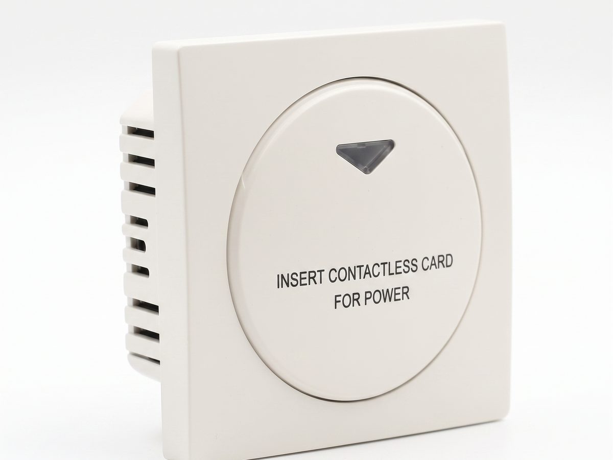
Hotel Key Card Switch — Guest Room Power Control
Hotel key card switch for guest room power control. RFID/IC card detection, insert-and-power, card removal time-delay power-off. 220V AC, 10A-16A, RS485 or dry contact. CE RoHS. OEM/ODM supplier.
This page already points to it as the next recommended reference.
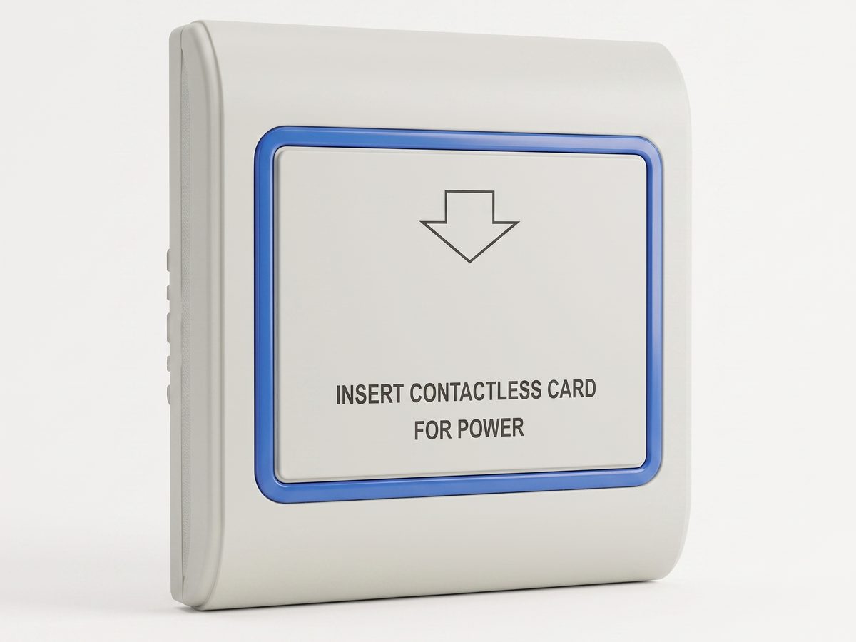
RFID Key Card Switch — Contactless 13.56MHz Guest Room Power Control
RFID key card switch with contactless 13.56MHz detection. Guest simply taps a card on the reader area to power the room, no insertion slot needed. Works alongside hotel door locks. CE RoHS. OEM/ODM supplier.
This page already points to it as the next recommended reference.
Related solutions
3Guest Room Management System Based on Card-Controlled Power
A practical guest-room management system for controlling room power through key card switches, contactors, and clearly documented operating rules.
It supports the same product context: Hotel Key Card Switch — Guest Room Power Control.
Hotel Energy Saving with Guest-Room Power Switching
A hotel energy-saving solution that uses card-controlled room power to prevent lights, air conditioning, and selected outlets from running unnecessarily.
It supports the same product context: Hotel Key Card Switch — Guest Room Power Control.
Hotel Room Power Control with Key Card Switches
A practical hotel room power control solution for switching guest-room lighting, air conditioning, and outlets from an authorized room card.
It supports the same product context: Hotel Key Card Switch — Guest Room Power Control.
Related blog posts
3
Hotel Key Card Switch: Types, Models, and How to Specify
A hotel key card switch spans universal, RFID, TTLOCK, BLE, and occupancy models. This guide to the key card / keycard switch family covers the head terms —…
It supports the same product context: Hotel Key Card Switch — Guest Room Power Control.

RFID vs NFC for Hotel Key Card Switches: Which Card Tech to Choose
RFID vs NFC for hotel key card switches comes down to range and lock-in: 125kHz / 13.56MHz RFID (MIFARE, Temic) is the hotel standard for room-bound power…
It supports the same product context: Hotel Key Card Switch — Guest Room Power Control.
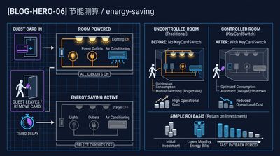
What Is a Hotel Key Card Switch and How It Saves Room Energy
A hotel key card switch is a wall device that powers a guest room when a card is inserted and cuts it when removed, typically saving 25–40% of room…
It supports the same product context: Hotel Key Card Switch — Guest Room Power Control.
Specify your hotel project with our engineers
Send your room count, ceiling type, and protocol preference. We will return a sample plan and quote within 24 business hours.
- Move from general guidance into a product or application discussion.
- Use RFQ when pricing, drawings, MOQ, or launch timing needs structure.
- Keep a direct contact path visible for fast clarifications and handoff.