Hotel Key Card Switch HVAC Integration: How to Control Air Conditioning Power
Hotel key card switch HVAC integration guide covering A/C power control, thermostat wiring, compressor delay-off, and contactor switching.
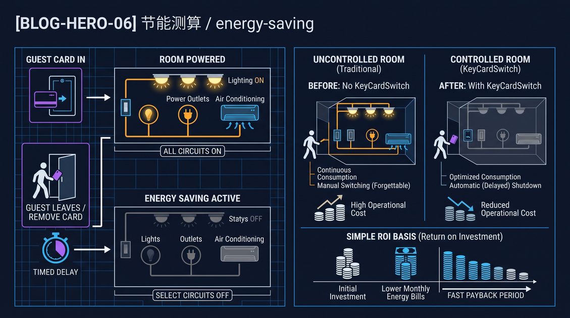
Hotel key card switch HVAC integration is the practice of tying a room's card-operated power switch to its air conditioning and heating circuits so that HVAC energizes only while a valid guest card is inserted. In a typical hotel key card switch HVAC integration, the switch reads the card at the entryway and closes a control circuit that powers the indoor HVAC unit alongside the lights and sockets, then opens that circuit after a short delay when the card is removed. The stated purpose is energy savings from not running the compressor and fan in an empty room, while the indoor wall thermostat still governs the actual setpoint and fan speed inside the conditioned space. Because air conditioning is usually the largest electrical draw in a guest room, the way the card switch couples to the A/C power feed determines both how much load the switch must switch and how safely the compressor shuts down.
What a Hotel Key Card Switch HVAC Integration Actually Controls
A hotel key card switch HVAC integration controls the power side of the room conditioning package rather than the temperature setpoint. When a valid card is inserted, the key card switch closes its relay or contactor and energizes the branch circuit that feeds the indoor unit, the wall thermostat, and usually the lighting and general sockets; when the card is removed, the same switch de-energizes that circuit so the HVAC compressor, circulation fan, and standby electronics stop drawing power. The indoor wall thermostat continues to read room temperature and command heating or cooling, but only while the conditioned circuit is live. This is a power-disconnect design, distinct from a smart-control design that talks to the A/C over a data bus. A basic hotel key card switch HVAC integration therefore protects the property against an unoccupied room running a compressor for hours, and it is the simplest retrofit because it adds a control interlock to the existing A/C branch feed rather than replacing the thermostat or installing a controller network.
The Split Between Power and Temperature Control
The cleanest way to understand the integration is to separate two jobs that are often confused. The key card switch is the power gate; the thermostat is the temperature brain. The thermostat reads the room sensor, compares it with the occupant's target, and decides whether the valve or compressor should run. The key card switch decides whether the whole conditioning circuit is allowed to be live at all. In hotel key card switch HVAC integration, the switch does not re-set the thermostat, does not read the room temperature, and does not disable the cooling when the window is open unless a dedicated sensor is added. It only opens and closes the circuit that the thermostat and the indoor unit share.
What Stays Live and What Does Not
A practical integration leaves certain loads on the always-on circuit and switches others through the card. The deadbolt lock, the smoke detector, the minibar, and the router usually stay powered continuously. The HVAC indoor unit, the lighting, the TV, and the general sockets typically sit behind the card switch. When an energy-saving version of the switch has a bypass, the installer wires the always-on loads to the bypass terminal and the guest-switched loads to the switched side. Documenting which circuits are which is essential, because a false trip or an emergency must never leave a corridor, exit light, or safety device dark.
Hotel Key Card Switch HVAC Integration: Energizing the HVAC Circuit
A hotel key card switch HVAC integration energizes the A/C circuit through a relay that closes when the card reader validates a card. The switch logic is simple: valid card inserted means room occupied, so the relay coil pulls in and the relay contacts close the live feed to the HVAC branch; card removed means the room is vacant, so the relay opens after a preset delay. The current path in a basic install runs from the mains distribution board, through the relay contacts, and on to the indoor A/C unit and thermostat. The card reader itself only draws the small current needed for its electronics and the relay coil, so the flush wall panel stays low-current even when the room load is a kilowatt-plus A/C unit.
Relay Ratings in the Context of A/C Loads
The relay inside or beside the switch must be rated for the inrush and running current of the A/C unit it starts. An R22 or R410A window package in a small room can draw several amperes steady-state but far more on compressor start because of the locked-rotor surge. Two relay sizing rules dominate a hotel key card switch HVAC integration: the continuous current rating must exceed the normal full-load current of the HVAC circuit, and the making capacity must tolerate the start surge without welded contacts. Standard switch relays are commonly 20 to 30 amps AC. When the room uses a bigger split unit or a self-contained package that exceeds that current, the installer moves to a contactor, covered later in this guide.
| HVAC device | Typical full-load range | Typical start surge | Suggested switching |
|---|---|---|---|
| Small split indoor/outdoor pair | 3–8 A | 4–6x full-load | 16–20 A relay |
| Guest-room package A/C (wall/window) | 6–15 A | 5–7x full-load | 20–30 A relay |
| Fan-coil unit (FCU) | 0.6–3 A | low blow of fan | 10–16 A relay |
| Large VRF indoor unit | 1–5 A per indoor, 30–60 A outdoor | high on outdoor | contactor on outdoor |
Wire Gauge for the Switched Circuit
The conductors running from the relay contacts to the A/C unit must be sized to the branch circuit, not to the tiny current the card reader uses. A hotel key card switch HVAC integration introduces an interlock point in the branch feed, so every code value that applies to that branch also applies at the new switching point: conductor size, overcurrent protection, terminal tightness, and insulation. Many installations land the relay in a junction box near the panel and run the switching pair to the card plate, keeping the high-current wiring in protected conduit. Always confirm the rated current of the relay against the breaker and the cable before energizing the circuit.
Delay-Off Timing in Hotel Key Card Switch HVAC Integration
Delay-off timing is one of the most important design choices in a hotel key card switch HVAC integration, because it determines what happens to the compressor when the card leaves the reader. A short delay, commonly 10 to 15 seconds, simply clears the room of the refrigeration load before the power drops. A longer delay, up to a few minutes, keeps the indoor fan coasting so moisture continues to drain and the coil finishes shedding condensate. The delay is settable on most energy-saving key card switches and should be chosen together with the HVAC manufacturer's guidance, because cutting a compressor mid-cycle is what causes slugging, liquid refrigerant return, and premature bearing wear.
Why Compressor Protection Demands a Delay
The physics behind the delay is that an A/C compressor must not restart against a high-pressure head that has not equalized. If the key card switch cut power instantly at card-out and a guest reinserted the card a minute later, the relay would try to restart the compressor while the discharge and suction pressures were still far apart, drawing a large starting current against a hard load. The standard hotel key card switch HVAC integration answers this with a locked-in delay-off that prevents the relay from re-closing for a fixed window even if the card returns immediately. This is separate from the drop-out delay; it is a restart lockout. On the simplest units the restart protection is left to the compressor's own thermal or pressure switch, but a well-designed integration adds its own minimum-off timer.
Setting the Delay for Different HVAC Types
The ideal delay differs by equipment. A fan-coil unit with a small water valve can shut nearly immediately because there is no vapor-compression start surge. A mini-split compressor benefits from a pre-shutdown fan run to drain condensate. A multi-split or VRF system has its own internal minimum-off protection and should be told to stop through its own control rather than being hard-disconnected, as described in the VRF section. A practical default used across the industry is 10 to 15 seconds of drop-out delay plus a restart lockout of 3 to 5 minutes, and a longer 1- to 2-minute pre-off fan run for units that support it.
| HVAC type | Suggested drop-out delay | Suggested restart lockout |
|---|---|---|
| Fan-coil unit | 0–10 s | none needed |
| Mini-split / wall split | 10–15 s | 3–5 min |
| Package / window A/C | 15–30 s | 3–5 min |
| VRF / VRV indoor | hand off to system | system-managed |
Hotel Key Card Switch HVAC Integration: Contactor Switching for High-Power Loads
Not every A/C circuit can be switched by the relay inside a flush key card switch. In a hotel key card switch HVAC integration for a large room, a suite, or a building-level HVAC distribution, the card switch should drive a contactor that carries the real load. A contactor is a heavier electromechanical switching device rated for higher current and higher inrush than a panel-mounted relay. The card switch supplies only the contactor coil; the contactor contacts carry the A/C feed. This keeps the wall plate low-current while allowing the integration to switch 30, 40, or 60 ampere circuits safely and with far better tolerance for the locked-rotor surge of a large compressor.
Contactor Coil Circuit
The contactor coil is wired in series with the key card switch's switching output. When the guest card is inserted, the relay inside the card switch closes and sends power to the contactor coil, the contactor pulls in, and its main contacts close the HVAC branch. When the card is removed, the relay opens, the coil drops out, and the contacts open. Because the coil can draw 30 to 120 milliamps depending on size, the card switch must be rated for the coil load as well as its own circuit. Confirm that the key card switch output can interrupt the contactor coil cleanly, and add a snubber or freewheeling diode across an AC coil where recommended.
Sizing a Contactor for an A/C Unit
Contactor sizing follows the nameplate of the A/C unit. Match the contactor's full-load amp rating and horsepower or kilowatt rating to the compressor and condenser fan combination on the plate, not to a guess from the room size. Include the fan-coil current if the contactor switches the whole indoor unit. The contactor should be rated for the ambient temperature of the enclosure and for the number of switching operations the room will see, because a card switch can cycle the contactor many times a day, and contact life falls as switching frequency and load rise.
| Sizing input | Source | Why it matters |
|---|---|---|
| Full-load amps | A/C nameplate | continuous current the contacts must carry |
| Locked-rotor / start amps | A/C nameplate | surge the contacts must make without welding |
| Kilowatt / horsepower | A/C nameplate | chosen by local code for motor loads |
| Enclosure temperature | site survey | derating of contactor and cable |
| Cycling frequency | expected card-in/card-out | contactor electrical endurance |
Hotel Key Card Switch HVAC Integration: Thermostat and Temperature Controllers
A hotel key card switch HVAC integration must work harmoniously with the room thermostat, because both devices sit in the same wall and both relate to the A/C. The standard arrangement is that the key card switch sits upstream of the thermostat in the power path: the card switches the live feed, and the thermostat, powered from that switched feed, switches the cooling or heating call inside the unit. In this arrangement the thermostat has no power when the room is empty, so it cannot call for cooling and the compressor cannot run; when the guest inserts the card, the thermostat wakes and controls temperature normally.
Two-Terminal Versus Multifunction Thermostats
The integration behaves differently depending on how the thermostat receives its controls. A simple electromechanical or low-voltage thermostat with two terminals for the call is the easiest to integrate, because the card switch merely has to control the power supply and the thermostat does the rest. A programmable or WiFi thermostat that must stay powered to remember its schedule and keep its clock must be fed from the always-on circuit or given a battery backup, otherwise every card-out wipes its programming and it renegotiates on reentry. In a hotel key card switch HVAC integration, decide explicitly where the thermostat gets its supply, and keep the thermostat's own controls out of the high-current switching path.
Controlling the Compressor Call Rather Than the Power
On more advanced equipment, the cleaner integration is to have the card switch signal the thermostat or the unit's control board rather than hard-cutting the power. Instead of disconnecting the A/C feed, the key card switch delivers a dry contact or a digital occupancy signal that tells the controller to go to standby. This approach avoids the thermal shock of a hard power cut and preserves the unit's internal delay and self-diagnostics. It requires a key card switch with an auxiliary output or a dry contact, and it is the preferred route for equipment that does not tolerate raw power cycling, such as many VRF indoor units. See the equipment-specific sections below for when to use a power cut versus a control signal.
| Integration style | Switch role | Best for |
|---|---|---|
| Power-cut interlock | card switch opens HVAC branch feed | small splits, packages, FCUs |
| Occupancy dry contact | switch tells controller to standby | VRF, VRV, smart indoor units |
| Contactor-driven power | switch drives contactor coil | high-power or central circuits |
| Thermostat on switched feed | switch feeds thermostat + unit | basic electromechanical thermostats |
Hotel Key Card Switch HVAC Integration: VRF and VRV Systems
VRF and VRV systems (variable refrigerant flow/volume) present a special case in hotel key card switch HVAC integration because their indoor units do not like a raw mains power cut. A multi-split VRF has one outdoor unit feeding several indoor units through a refrigerant pipe network, and the outdoor unit schedules compressor capacity to match the indoor units that are calling. If the key card switch hard-disconnects one indoor unit's mains, the outdoor unit can misread that branch as faulted, log an error, or offset its capacity calculation. The recommended integration for VRF is therefore to use the key card switch to send an occupancy or standby signal to the indoor unit's controller rather than to chop its power supply.
The Occupancy Signal Path on VRF
Most VRF indoor units have a control input or a wired remote that accepts an on-and-off or standby command, and many accept an external dry contact for a forced-off condition. In a hotel key card switch HVAC integration on VRF, the switch's auxiliary output closes a dry contact that the indoor unit reads as remove-from-call, so the unit stops cooling but stays powered and stays healthy on the network. The outdoor unit then correctly sees that indoor unit as dormant rather than missing, and it de-allocates capacity without a fault alarm. This preserves the oil return and pressure equalization routines that protect the whole refrigerant loop.
Hard Power Cut as a Fallback
When the VRF indoor unit has no clean standby input, a hard power cut through a contactor is possible but must be done with discipline. The switch should hold the circuit closed long enough to complete the unit's shutdown cycle, and the contactor should not re-close too quickly on reentry because the unit's board needs to boot and its own minimum-off timer applies. In practice this means a hotel key card switch HVAC integration on VRF either uses a manufacturer-approved forced-off input or coordinates with a property controller, and it never relies on a 10-second drop-out delay to protect a VRF compressor.
| VRF integration method | What the switch does | Risk if done wrong |
|---|---|---|
| Forced-off dry contact | closes input the indoor unit reads as standby | none when wired to approved terminal |
| Standby via wired remote | switch triggers remote standby command | none |
| Hard contactor power cut | disconnects indoor mains after shutdown | network fault, capacity misread |
Hotel Key Card Switch HVAC Integration: Fan-Coil Units
Fan-coil units are common in hotels that use a central chilled-water or hot-water plant with a local fan and valve in each room, and they are the easiest HVAC load to integrate because there is no compressor to protect. A hotel key card switch HVAC integration on a fan-coil unit energizes the FCU fan and its water valve supply through the card switch, so an empty room stops its fan and closes its water valve. The chilled-water valve should be powered through the switched side so that the room does not keep heating or cooling while vacant, because a closed valve on the switched circuit prevents both unwanted conditioning and condensate dripping.
Valve and Fan Behaviour at Card-Out
When the card is removed, the fan-coil's power is cut and the valve de-energizes to its closed or fail-safe position. Choose a valve with a fail-closed action on loss of power so that water does not keep flowing through an unoccupied room. Because an FCU has a low inrush, a standard 10 to 16 ampere relay in the card switch is usually sufficient, and no contactor is needed unless the FCU is oversized. The drop-out delay for an FCU can be near zero, though a short 5-second run helps the valve seat and the condensate pan drain.
Speed Control and the Key Card Switch
Some fan-coil units have a three-speed fan switched at the wall. In this case the speed selector and the card switch work together: the speed selector picks the fan speed, and the card switch decides whether the FCU circuit is powered at all. Keep the speed selector on the switched side so everything de-energizes together, and keep the card switch output rated for the combined fan, valve, and control transformer draw. For thermostatically controlled FCUs the same upstream-position rule applies as for small splits: the card switch feeds the circuit and the room thermostat still decides the actual valve and fan operation.
Hotel Key Card Switch HVAC Integration: Wiring Configurations
The wiring of a hotel key card switch HVAC integration can be organized in a few repeatable configurations, and matching the right configuration to the equipment avoids both safety hazards and poor start behaviour. The three main patterns are a direct relay interlock for a single A/C branch, a contactor pattern for higher current, and a control-signal pattern for VRF or smart units. Each configuration has the same reader and card logic; only the switching hardware downstream of the card switch differs.
| Configuration | Downstream hardware | Current range | Equipment fit |
|---|---|---|---|
| Relay branch interlock | panel relay, switched A/C feed | up to 20–30 A | small split, window, FCU |
| Contactor interlock | contactor coil + main contacts | 20–60 A+ | suite, package, bigger circuit |
| Occupancy dry contact | auxiliary output to controller | signal only | VRF, VRV, smart indoor |
| Always-on + switched split | bypass terminal | mixed | DND, locks, router on bypass |
Step Sequence for a Relay-Contactor Interlock
Each configuration follows a repeated install sequence. For the common contactor interlock, first energize the contactor coil from the key card switch output and connect its main contacts in the A/C branch feed with the supply off. Second, fit the overcurrent protection and cable sized to the branch, and verify the contactor releases when the card is removed. Third, set the delay-off and restart lockout on the switch to match the HVAC type. Fourth, test with the A/C on a dummy or unoccupied run, checking that the compressor coasts down before contactor dropout and that the unit restarts cleanly on reinsertion. Fifth, label the contactor and the switched circuit so maintenance can trace the interlock.
Hotel Key Card Switch HVAC Integration: Sizing and Electrical Rules
Correct sizing is the difference between a hotel key card switch HVAC integration that runs for years and one that welds its contacts in a week. The three values that matter are the continuous load, the start inrush, and the available fault current at the branch. Every switching point added to the A/C feed must clear the same fault current the branch could see, so the relay or contactor interrupting rating must match the circuit. An undersized relay carrying an A/C start surge welds its contacts, and a relay with too low an interrupting rating can fail dangerously on a fault.
The Inrush Rule
The single most common field error is sizing a switch relay on the running amps of the A/C rather than on its start current. Because a compressor can draw several times its full-load current for the first few cycles, the relay contacts must make that surge repeatedly without welding or pitting. When the nameplate start current is not available and the unit is a motor load, apply a conservative multiplier and use the next relay or contactor size up. A hotel key card switch HVAC integration that appears fine on a bench test can fail in service solely because the start surge was never considered.
| Sizing decision | Correct rule |
|---|---|
| Relay continuous rating | above HVAC full-load amps |
| Relay make/break rating | handles compressor start inrush |
| Contactor rating | per nameplate FLA + surge |
| Conductor size | per switched branch, not reader draw |
| Interrupting rating | matches branch fault current |
Hotel Key Card Switch HVAC Integration: Common Installation Mistakes
Most failures in a hotel key card switch HVAC integration trace back to a small set of repeatable mistakes rather than to exotic faults. Wiring the always-on loads into the switched side is the most common error, locking out DND, smoke detectors, and the electronic lock. Sizing the relay on running amps instead of start amps is the second, causing welded contacts on the first heavy-cooling day. A third mistake is using a hard power cut on VRF or smart equipment that requires a standby signal. And a fourth is setting the delay-off too short for a split compressor, so every card-out beats the unit's own minimum-off timing.
Wiring the Bypass Wrong
The always-on and switched sides of the energy-saving key card switch are clearly marked, but in an unfamiliar panel the bypass and switched terminals are easy to swap. Confirm which terminal stays alive when no card is present by metering the terminals with the card out before connecting any load. Put only the true guest circuits on the switched side, and keep safety and identity loads on the bypass. Label each conductor at the panel so a later service call does not have to re-trace the whole routing.
Ignoring the Indoor Unit's Own Protection
Modern A/C indoor units carry their own printed minimum-off and self-diagnostics, and a key card switch that chops power roughly can defeat those protections. Verify from the unit manual whether the manufacturer expects a power-cut interlock or a commanded standby. When the manual forbids power cycling, switch to the occupancy dry-contact or contactor-plus-delay route. A hotel key card switch HVAC integration that respects the unit's own protection will produce far fewer error codes and a longer compressor life.
Hotel Key Card Switch HVAC Integration: Energy Efficiency Principles
The energy case behind a hotel key card switch HVAC integration rests on the observation that a guest room spends a large share of its day vacant, between checkout, during cleaning, and while the guest is out. An air conditioner left to hold a target temperature in that empty room keeps cycling its compressor and fan purely to cool air no one is using. Cutting the HVAC branch feed through the card switch stops that continuous standby load the moment the last guest leaves, and it restores it only when a valid card returns. The savings thus come mainly from eliminating run time and standby power in an unoccupied space, not from making the unit itself more efficient.
| Load type | Behaviour in an empty room | Effect of card switch cut |
|---|---|---|
| Compressor | keeps cycling to hold setpoint | stops when circuit opens |
| Indoor circulation fan | keeps running | stops at delay-off |
| Standby electronics | power supply stays on | powered off |
| Water valve (FCU) | keeps circulating chilled water | closes with the circuit |
Why the Switch Is Faster to Adopt Than a Smart Controller
A hard power interlock is cheap, predictable, and requires no network, and that is why it remains the default in a hotel key card switch HVAC integration. A smart-controller design that reads occupancy, logs room state, and throttles A/C setpoints through a cloud or local gateway delivers finer control, but it depends on a controller, stable power, and commissioning that a standalone switch does not. For a property that wants a reliable baseline with no software dependency, the key card switch is the lowest-risk starting point, and it can be layered with a controller later without rebuilding the wiring.
Hotel Key Card Switch HVAC Integration: Comparing Guest Room A/C Controls
Two broad philosophies define how the A/C is controlled around a key card switch, and choosing the right one changes the hardware you specify. The first is a power-cut interlock, where the card switch simply opens the A/C branch feed; it is simple, low-cost, and works with basic equipment. The second is a control-signal approach, where the card switch tells the unit's controller to enter standby while keeping the unit powered; it preserves the unit's intelligence and suits VRF and smart equipment. The decision is driven by the equipment installed and by whether the property wants raw switching or intelligent handoff.
| Comparison | Power-cut interlock | Control-signal handoff |
|---|---|---|
| Hardware | relay or contactor | auxiliary dry contact |
| Equipment fit | split, package, FCU | VRF, VRV, smart indoor |
| Cost | lower | higher |
| Network dependency | none | usually none for dry contact |
| Compressor protection | via delay + lockout | via unit's own controller |
| Commissioning effort | low | moderate |
Hotel Key Card Switch HVAC Integration: Outputs and Accessories
The hardware choices inside the wall plate determine how cleanly a hotel key card switch HVAC integration connects to the A/C feed. A standard key card switch offers a switched output that follows the card state, and an energy-saving variant adds a bypass output for loads that must stay live. For HVAC work the two outputs matter most because many installers unintentionally put the whole room on one output and then discover the smoke detector or lock is dark when the card is out. The accessory kit typically includes relay sockets, terminal blocks, and labels that keep the panel organized.
Switched Versus Bypass Output
The switched output is the one tied to the card state: it energizes when a valid card is inserted and de-energizes at delay-off when the card leaves. The bypass output stays live continuously regardless of card state. In HVAC integration, route the A/C branch typically through the switched output, and route the always-on services through the bypass output. If a bathroom extractor or a small ventilation fan should also stop with the room, put it on the switched side; if an air quality monitor or router must stay on, put it on the bypass side.
Choosing Relay Rating and Thermal Capacity
Because the A/C branch may draw a few amperes and sees start surges, prefer a key card switch whose switching section is rated for the HVAC current with margin. A 20 to 30 amp switched rating on the output suits a normal guest-room split or FCU, while higher or longer branch circuits move to a contactor. Check the thermal rating of the panel and the enclosure, because a thermally under-rated unit can heat the wall plate when the HVAC load runs for long hours in a warm climate. Heat is the enemy of contact life, and ventilation around the relay housing matters more in ceiling voids and compact boxes than in an open panel.
Hotel Key Card Switch HVAC Integration: Maintenance and Troubleshooting
A hotel key card switch HVAC integration needs little routine attention, but the few checks that matter are the ones that prevent a hot-room complaint. Periodically confirm that the bypass loads stay live when no card is present, that the switched A/C circuit actually drops out after delay-off, and that the relay or contactor contacts show no burning or weld. A burning smell, a hot plate, or an A/C that will not start on card-in usually points to a contact or terminal problem rather than to the card reader, so trace the load path before blaming the logic.
| Symptom | Likely cause | First check |
|---|---|---|
| A/C stays on after card-out | bypass miswired or contact welded | metering the output terminals |
| A/C will not start on card-in | relay worn or coil not pulling in | output voltage at card-in |
| Wall plate warm | thermal derating, heavy load | load vs relay rating |
| A/C starts then faults | start surge welded the contacts | contact condition + inrush sizing |
| VRF logs a fault | hard power cut where standby was needed | switch to forced-off signal |
A Design Checklist for Hotel Key Card Switch HVAC Integration
Because the integration touches supply, switching, and control, a checklist keeps the design consistent across hundreds of rooms. Confirm the HVAC type and its switching requirement first, then the load and inrush, then the switching hardware, then the wiring separation between always-on and switched circuits, and finally the delay-off and lockout settings. Two final questions close the design: whether the equipment needs a power cut or a control signal, and whether the switch has a bypass for the loads that must stay live.
| Check item | Pass condition |
|---|---|
| HVAC type identified | split / package / FCU / VRF known |
| Switching requirement known | power cut or standby signal chosen |
| Relay or contactor rated | covers FLA and start inrush |
| Always-on vs switched separated | safety and identity stays live |
| Delay-off and lockout set | matches compressor minimum-off |
| Wiring labeled | every conductor traceable |
Hotel Key Card Switch HVAC Integration: Frequently Asked Questions
Does the key card switch replace the thermostat?
No. The key card switch controls the power side of the HVAC circuit; the thermostat keeps controlling the temperature and the cooling call inside the conditioned space. In a typical hotel key card switch HVAC integration the switch sits upstream and the thermostat rides on the switched feed.
Can one key card switch control the air conditioner of a suite?
A suite with several A/C units can be covered by one switch if the switched output is wired to a contactor or to a bus that energizes all the conditioning circuits together. Confirm the combined load against the contactor rating, because removing several cards at once on a large suite pushes the start inrush higher.
What delay should I set so the compressor is not damaged?
Set the drop-out delay so the compressor finishes its coast-down, commonly 10 to 30 seconds, and add a restart lockout of 3 to 5 minutes so a quick reentry cannot restart against un-equalized pressure. Match both to the HVAC manufacturer's minimum-off requirement, because the unit's own protection overrides anything a faster switch setting claims to do.
Part of this article content is generated by AI and optimized for professional accuracy and readability.
Not sure which sensor fits your project?
Talk to our mmWave application engineers for a free consultation.
Find the right presence sensor for your hotel project
Compare the 3 protocols, check hotel-specific case studies, and download the installation guide
Related products
3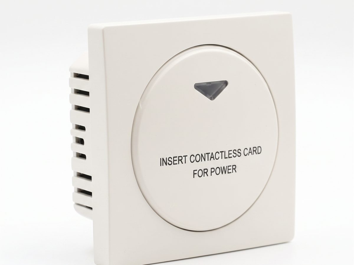
Hotel Key Card Switch — Guest Room Power Control
Hotel key card switch for guest room power control. RFID/IC card detection, insert-and-power, card removal time-delay power-off. 220V AC, 10A-16A, RS485 or dry contact. CE RoHS. OEM/ODM supplier.
This page already points to it as the next recommended reference.
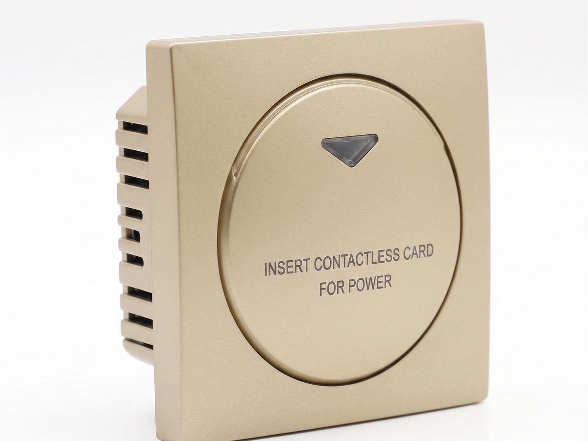
Hotel Energy Saving Switch — Insert-Card Guest Room Power Control
Hotel energy saving switch that powers a room on card insertion and cuts power after a card-removal delay, pairing with HVAC to stop empty-room waste. 220V AC, 10A-16A, RS485 or dry contact. CE RoHS. OEM/ODM supplier.
This page already points to it as the next recommended reference.
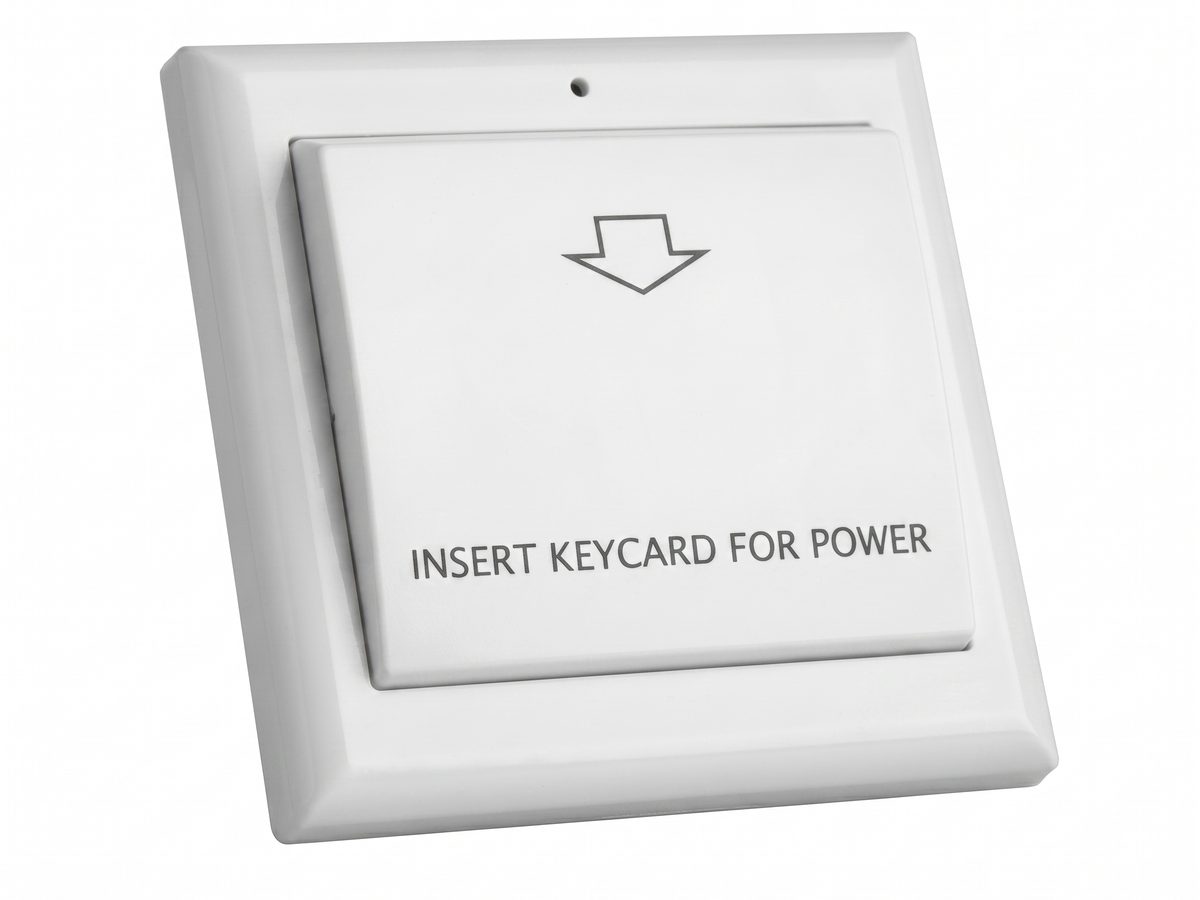
Key Card Switch Accessories — Face Plates, 86 Boxes, Contactors and Power
Key card switch accessories for the 86 box install: face plates, 86 box mounting bases, contactors for high-load HVAC, power supplies, and RS485 hubs. Choose accessories to complete any 86 box key card switch project.
This page already points to it as the next recommended reference.
Related solutions
3Hotel Room Power Control with Key Card Switches
A practical hotel room power control solution for switching guest-room lighting, air conditioning, and outlets from an authorized room card.
This page already points to it as the next recommended reference.
Guest Room Management System Based on Card-Controlled Power
A practical guest-room management system for controlling room power through key card switches, contactors, and clearly documented operating rules.
It supports the same product context: Hotel Key Card Switch — Guest Room Power Control.
Hotel Energy Saving with Guest-Room Power Switching
A hotel energy-saving solution that uses card-controlled room power to prevent lights, air conditioning, and selected outlets from running unnecessarily.
It supports the same product context: Hotel Key Card Switch — Guest Room Power Control.
Related blog posts
3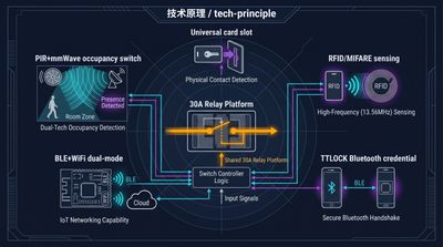
Hotel Key Card Switch: Types, Models, and How to Specify
A hotel key card switch spans universal, RFID, TTLOCK, BLE, and occupancy models. This guide to the key card / keycard switch family covers the head terms —…
It supports the same product context: Hotel Key Card Switch — Guest Room Power Control.
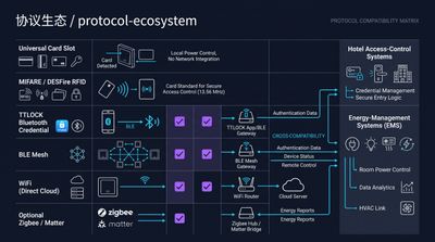
RFID vs NFC for Hotel Key Card Switches: Which Card Tech to Choose
RFID vs NFC for hotel key card switches comes down to range and lock-in: 125kHz / 13.56MHz RFID (MIFARE, Temic) is the hotel standard for room-bound power…
It supports the same product context: Hotel Key Card Switch — Guest Room Power Control.
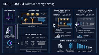
What Is a Hotel Key Card Switch and How It Saves Room Energy
A hotel key card switch is a wall device that powers a guest room when a card is inserted and cuts it when removed, typically saving 25–40% of room…
It supports the same product context: Hotel Key Card Switch — Guest Room Power Control.
Specify your hotel project with our engineers
Send your room count, ceiling type, and protocol preference. We will return a sample plan and quote within 24 business hours.
- Move from general guidance into a product or application discussion.
- Use RFQ when pricing, drawings, MOQ, or launch timing needs structure.
- Keep a direct contact path visible for fast clarifications and handoff.