Hotel Key Card Switch Door Lock Integration: A Practical Guide
Learn how a hotel key card switch works alongside Onity, VingCard, Assa Abloy, and SALTO locks, including cards, wiring, wireless doors, and retrofit coordination.
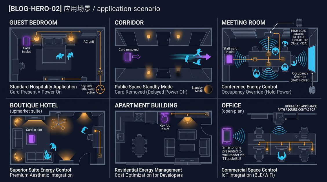
Hotel key card switch door lock integration is usually a coordination problem rather than a direct electronic connection. The lock reader verifies a credential at the entrance, while the room switch controls selected loads after a guest presents an approved card inside the room. In most projects, both devices can accept the same card format without sharing data, firmware, or a network. The switch is specified by card technology, voltage, load, and contact arrangement; the lock is specified by its credential family, cylinder hardware, access rules, and offline or online architecture. A successful design therefore confirms card compatibility, electrical separation, mounting position, and commissioning responsibilities before installation. This guide explains how common hotel lock families work alongside key card switches, when integrated wiring is unnecessary, how wireless locks change the retrofit sequence, and how owners, lock vendors, electrical contractors, and switch suppliers can avoid handover disputes.
Hotel key card switch door lock integration architecture
Hotel key card switch door lock integration uses two coordinated but normally independent systems: the door lock grants entry, while the room switch enables selected electrical loads. A switch may read a contact card or RFID credential, and a lock may use a programmed credential, but a shared card does not imply a data cable or common controller. Typical controlled loads include lighting, sockets, fan-coil enable, and a contactor for a larger circuit. The lock remains responsible for access, privacy, mechanical release, and credential rules. The switch remains responsible for its relay, timing, and room circuit. This boundary improves resilience because a switch fault should not prevent entry and a lock battery issue should not leave the room power system uncontrolled. Architecture drawings should show both devices, their supplies, their circuits, and the exact guest sequence. If an owner requests a door signal, central supervision, or automatic occupancy logic, that is an additional controls project and must be specified separately.
Separate functions before selecting products
A room power switch is commonly placed near the entrance so the guest can find it while entering. Its output may feed lighting scenes, socket groups, or a contactor that controls a larger load. The exact circuit arrangement belongs on the electrical design, and the switch supplier should receive the final voltage and current schedule. A door lock reader normally sits on the door exterior and is optimized for access, weather exposure, security, and battery service. Placing a power switch in that security chain can create an undesirable single point of failure. A clean separation lets the lock keep its access function during a room power-control repair.
Integration language can be misleading in specifications. In one project, integration may mean one card works in two readers. In another, it may mean a direct dry contact, a controller, or a software event. These are materially different scopes. Write the intended sequence in plain language: present card, enable selected loads, remove card, apply delay, retain essential circuits. Then state whether the door reader must send any signal. If it does not, the low-voltage drawings should show two independent systems and a shared commissioning test only.
The switch should not be used as a security indicator unless it has been specifically engineered and tested for that purpose. A card left in a holder does not prove that the authorized guest is present. Likewise, a light turning off does not prove that the room is vacant. This distinction matters for housekeeping, maintenance, emergency response, and accessibility. Owners should describe the switch as a power-control device and keep door access decisions within the lock system.
A room standard should include a one-line diagram, a card sample photograph, a mounting detail, and a sequence of operation. It should identify circuits that must remain live, such as refrigeration, life-safety equipment, or selected charging outlets where applicable. Review the standard with the door lock vendor and the electrical engineer before repeating it across floors. This small approval step prevents a brand-compatible reader from being installed on an unsuitable circuit.
Hotel key card switch door lock integration and shared cards
A shared card means one physical guest credential can be accepted by both the door lock and the in-room switch, but it does not mean the two devices are electronically integrated. The card must present a technology and reading behavior that each device supports. Some switches respond to a card's physical presence and do not validate the encoded guest identity; others are designed for a specific RFID family and may reject an incompatible chip. A lock may use encrypted sectors, a programmed serial number, or a proprietary credential profile. Before ordering, obtain the lock supplier's credential specification and ask the switch supplier which card types it reads. Test the actual card stock, including key sleeves and printed overlays, because thickness and antenna position can affect insertion or read distance. The decision should be recorded before procurement, because a card reader, door lock, and room power circuit can each be correct on its own while still failing as a guest workflow. A sample-room test is practical proof.
Card technology is the real interface
Visual similarity between cards is not evidence of technical compatibility. Two cards may have the same printed artwork while using different chips, frequencies, memory layouts, or reader behaviors. Ask for the card part number, technology, operating frequency where applicable, and whether the lock encodes credentials in a protected sector. Ask the switch supplier to state its supported families in the same terminology. If a supplier cannot identify the reading method, require a sample test before purchase.
The switch may be intentionally less selective than the lock. Some hotel energy switches detect a physical card shape or a broad RFID presence, while the lock checks whether a credential is authorized for a particular door and time. That can make the room power experience convenient but also means a staff card, expired card, or another compatible token might activate the switch. The operating policy should decide whether that behavior is acceptable. A stricter reader can be specified if the project needs identity validation.
Card sleeves, key fobs, mobile credentials, and metal wallets deserve explicit testing. A sleeve can prevent a contact card from seating fully or change the distance to an RFID antenna. A fob may be accepted by the door but not fit a slot-style switch. A phone credential may unlock a wireless door without presenting a card at all. If the owner wants phone-based entry and automatic room power, that is a separate user-experience and controls requirement, not an automatic result of lock compatibility.
Keep a controlled card sample in the project records. Label it with technology, issue date, and intended use, and use it during factory and site acceptance tests. Do not substitute a visually similar card from a local printer. When a hotel changes lock credentials later, the switch behavior must be retested even if the faceplate and wiring remain unchanged.
Same card, different authorization
A lock can reject a lost or expired card while a broad-presence switch still responds to it. That is not necessarily a defect; it is a result of different functions. The project team should decide whether the room switch should accept all compatible tokens, only a narrow card family, or a validated credential. Each option affects reader cost, guest experience, and service procedures. Put the decision in the room standard rather than leaving it to an installer.
Hotel key card switch door lock integration with Onity locks
Onity locks and a hotel key card switch generally work alongside one another as separate room devices. The practical question is not whether the switch is branded Onity, but whether it reads the same credential format used by the property's door locks. An Onity deployment may include different generations of readers, cards, and encoder practices, so a project should verify the installed lock model and card technology rather than rely on the brand name alone. The door lock normally handles access decisions at the door; the switch can use a compatible card as a room-presence trigger or simply detect a card token. No lock-to-switch data cable is normally required for that basic behavior. During a retrofit, keep the lock vendor responsible for door hardware, reader programming, and access testing, while the electrical contractor handles switch circuit wiring.
Onity coordination questions
Ask the Onity contractor for the exact reader family, card sample, credential frequency where applicable, and whether staff cards differ from guest cards. Ask the switch supplier whether its reader detects the same technology and whether it validates identity or merely senses presence. Record the answer in a compatibility matrix. Avoid saying that every Onity lock and every switch share a universal interface, because lock generations and card configurations differ.
A joint sample-room test confirms that guest, housekeeping, and emergency cards behave as intended. Test an authorized guest card at the door and in the switch. Test a card that is physically similar but not approved. Test card removal, delay, and essential circuits. The Onity installer should sign the access portion and the electrician should sign the power portion. A single combined checklist keeps the guest workflow visible without assigning the wrong trade responsibility.
Hotel key card switch door lock integration with VingCard systems
VingCard lock systems and hotel key card switches can be deployed in the same room when the switch is selected for the site's card family and electrical design. VingCard is a product ecosystem rather than a universal card specification, and properties may have different reader generations or credential configurations. Ask for the exact card technology, not only the lock brand, before approving a switch. The lock reader can remain responsible for access at the corridor door, while the switch controls lighting, sockets, fan-coil enable, or a contactor according to the room power design. This arrangement normally uses no shared communications cable. The important coordination points are card presentation, wall-box dimensions, circuit grouping, and the distinction between a switch that merely detects insertion and one that validates a credential. The decision should be recorded before procurement, because a card reader, door lock, and room power circuit can each be correct on its own while still failing as a guest workflow. A sample-room test is practical proof.
VingCard project workflow
A mock-up should include the actual VingCard-issued card, the selected faceplate, and the final electrical load so installers do not discover incompatibility after rooms are finished. Confirm whether a card must be inserted, tapped, or held near the switch. Confirm whether a sleeve changes the reading behavior. Confirm that the switch's contact rating is suitable for the load or for the selected contactor coil. The lock installer should not be asked to approve mains wiring, and the electrician should not be asked to change credential programming.
When a property has several buildings or renovation phases, make a card inventory by phase. A new VingCard reader may use a different credential family from an older building. The same printed artwork can hide this difference. Test each phase's cards with each proposed switch. If one switch must support multiple card families, obtain written support details and test all families rather than assuming a universal reader.
Hotel key card switch door lock integration with Assa Abloy locks
Assa Abloy hotel locks can work alongside a compatible key card switch when both devices support the credential format chosen by the property. The same-card outcome depends on card technology, reader configuration, and the switch's sensing method; it is not guaranteed by the Assa Abloy name alone. Confirm whether the lock uses a contact card, 13.56 MHz RFID credential, or another format, and ask how staff credentials differ from guest cards. The lock usually remains a battery-powered or locally powered access device at the door. The room switch remains part of the low-voltage control and mains-load installation inside the room. Keeping those boundaries clear avoids an unnecessary cable between the door and the switch. The decision should be recorded before procurement, because a card reader, door lock, and room power circuit can each be correct on its own while still failing as a guest workflow. A sample-room test is practical proof.
Assa Abloy retrofit checks
For a renovation, record door numbers, lock models, card samples, and switch locations in one room schedule. Then test entry, power activation, card removal delay, and fail-safe behavior with the lock installer and electrician present. Verify that the proposed switch fits the existing wall box and does not conflict with a reader, thermostat, luggage bench, or door trim. If the door lock is wireless or battery powered, do not infer that the room switch can receive an entry event.
The specification should distinguish card compatibility from official cooperation. It is accurate to say that the switch works alongside a lock when the card format is supported and the devices pass the project test. It is not accurate to imply a joint product, certified interoperability, or a proprietary data link unless the responsible manufacturers have documented that exact arrangement.
Hotel key card switch door lock integration with SALTO locks
SALTO access systems and hotel key card switches are compatible as neighboring functions when the switch reader supports the card technology used by the SALTO installation. SALTO projects can vary by credential family, lock hardware, and operating model, so the card sample and reader specification are more useful than a generic brand-level assumption. A guest may use one card for the door and room switch, yet the switch may only detect the card's presence rather than check its permissions. That distinction should be explained to the owner: removing a card can turn off a room circuit even if the card is no longer valid at the door. Basic room power control does not require the switch to connect to the lock, a controller, or a software service. The decision should be recorded before procurement, because a card reader, door lock, and room power circuit can each be correct on its own while still failing as a guest workflow. A sample-room test is practical proof.
SALTO commissioning boundaries
Coordinate the switch location with door swing, luggage movement, and accessibility clearances, while the SALTO contractor validates lock handing, audit behavior, and access credentials. Commission both systems using the property's real cards and exception cards. Confirm that the card can be presented comfortably, that a sleeve does not block the reader, and that the switch does not respond to an unintended nearby token.
The owner should decide how housekeeping cards, maintenance cards, and emergency credentials behave. A switch that detects a compatible token may energize a room for a staff member even when the SALTO lock would apply a different access rule. That behavior can be acceptable, but it must be stated. If it is not acceptable, specify a more selective reader and test it with the actual credential set.
Hotel key card switch door lock integration wiring decisions
In a standard installation, hotel key card switch door lock integration does not require a data cable between the room switch and the door lock. The switch is wired into the room's designated power-control circuit, commonly through a relay or contactor when the load exceeds the switch rating. The lock is installed and powered according to its own hardware design, often with batteries or a dedicated access-control supply. A shared card provides a human workflow link, not a communications link. Integrated wiring becomes a separate design request when the owner wants a central controller, a door-position signal, a hardwired emergency release, or a custom logic sequence. The decision should be recorded before procurement, because a card reader, door lock, and room power circuit can each be correct on its own while still failing as a guest workflow. A sample-room test is practical proof.
When a cable is actually justified
Those requirements should be shown on electrical and low-voltage drawings with cable type, termination, power source, isolation, and testing responsibility. Never connect a lock output to a switch terminal simply because the terminals look similar. Confirm voltage, current, contact type, polarity, and local code requirements before energizing any circuit. A dry contact, powered output, and communication bus are not interchangeable interfaces.
A typical switch circuit may contain a protective device, the switch or relay, a contactor coil, and one or more controlled circuits. The lock may have its own battery, reader wiring, or access-control supply. Keep mains conductors, low-voltage conductors, and door hardware cabling routed and terminated according to the engineer's drawings and applicable local rules. The switch supplier can explain terminal limits, but the project electrical engineer approves the installation method.
Wiring comparison
| Integration dimension | Independent room switch and lock | Direct signal design | Shared card only |
|---|---|---|---|
| Door-to-switch data cable | Normally not required | Required if specified | Not required |
| Main interface | Card presentation and separate power circuits | Dry contact, controller, or defined bus | Same card technology |
| Access decision | Door lock | Door lock or approved controller | Door lock |
| Room power decision | Switch logic | Engineered control logic | Switch logic |
| Commissioning lead | Electrician with lock vendor sample | Controls engineer plus both trades | Electrician and lock vendor |
| Main risk | Wrong card or load assumption | Incorrect interface or isolation | Different card formats |
Hotel key card switch door lock integration for wireless locks
Wireless hotel locks usually simplify the physical retrofit because the door reader does not need a cable to the in-room switch. The wireless lock still needs a credential plan, while the switch needs a room power circuit and a suitable card reader. Since the devices do not exchange a live signal, a wireless door lock does not automatically tell the switch that a guest entered. The switch reacts to its own card presentation, timer, or configured sensing behavior. This can be acceptable for a simple guest-room workflow, but owners should understand edge cases such as a guest entering with a phone credential, a staff member using a different card, or a card being left in the switch after checkout. The decision should be recorded before procurement, because a card reader, door lock, and room power circuit can each be correct on its own while still failing as a guest workflow. A sample-room test is practical proof.
Wireless retrofit sequence
Coordinate wireless lock commissioning, battery access, radio survey, and switch installation as parallel work packages. The room mock-up should test the actual wireless lock credential, the switch's card response, and the selected load-control sequence without implying that one device supervises the other. Check door alignment, latch movement, battery replacement clearance, and signal conditions separately from the room's electrical test.
Wireless access reduces one category of cabling but does not eliminate coordination. The electrician still needs a safe route to the switch, and the lock contractor still needs access to the door and frame. Avoid placing a switch where a metal door, cabinet, or decorative panel shields an RFID reader. Test with the finished wall and furniture, not only with an unfinished mock-up.
Hotel key card switch door lock integration retrofit coordination
A retrofit succeeds when the existing lock system, new switch, and room wiring are surveyed before procurement. Start with a room-by-room inventory: door lock brand and model, card technology, switch cut-out, supply voltage, controlled loads, distribution-board space, and access dates. Invite the lock contractor, electrical contractor, general contractor, and switch supplier to approve one sample room. The lock contractor confirms cards and access behavior; the electrical contractor confirms circuit topology and isolation; the switch supplier confirms reader compatibility and terminal limits. Agree who supplies cards for testing and who signs the functional checklist. Preserve door hardware and lock firmware unless a documented change is required. The decision should be recorded before procurement, because a card reader, door lock, and room power circuit can each be correct on its own while still failing as a guest workflow. A sample-room test is practical proof.
Retrofit interface matrix
| Item to confirm | Door lock contractor | Electrical contractor | Switch supplier | Owner or general contractor |
|---|---|---|---|---|
| Installed lock model | Confirm | Record | Review card requirement | Approve schedule |
| Actual card sample | Provide | Test | Test reader | Approve guest workflow |
| Door hardware | Install and test | Avoid changes | No responsibility | Coordinate access |
| Room circuit | Record interface only | Design and wire | State terminal limits | Approve loads |
| Sample room | Access test | Electrical test | Reader test | Sign acceptance |
| Room release | Sign lock result | Sign circuit result | Sign product result | Close defects |
If the renovation changes cards, test existing doors before distributing new credentials. Sequence dusty demolition before installing readers and faceplates, then protect finished surfaces during cable pulling. A controlled pilot reduces repeated room entry and exposes card, mounting, and load issues while corrections are still inexpensive. Keep a photographic record of the approved location so later rooms do not drift from the standard.
Managing trade timing
The lock contractor may finish doors weeks before the electrician reaches the final room circuits. The switch supplier may be asked for an answer without seeing the actual card. The owner may approve a brand based on a previous property with a different credential family. A written interface matrix resolves these gaps. It lists device, purpose, card input, power source, cable requirement, responsible trade, test method, and acceptance evidence. It also identifies what is explicitly not included, such as direct lock control or an assumption that every credential type will activate power.
Hotel key card switch door lock integration commissioning checklist
Commissioning should prove the complete guest workflow while keeping access control and power control tests separately traceable. For each room, record the lock model, switch model, card type, circuit identifier, and approved load. Test a valid guest card at the door and at the switch, then test an invalid or incompatible card. Remove the card and verify the configured delay, while checking that essential circuits remain powered if the design requires them. Confirm the switch does not nuisance-trigger from a wallet, metal sleeve, or nearby card. Verify relay or contactor operation under the real load, not only with a lamp on a workbench. The decision should be recorded before procurement, because a card reader, door lock, and room power circuit can each be correct on its own while still failing as a guest workflow. A sample-room test is practical proof.
Functional test sequence
- Inspect the installed faceplate, card orientation, labels, and wall-box fit.
- Verify supply voltage and protective-device identification before inserting a card.
- Present the approved guest card at the door and record the access result.
- Present the same card at the switch and record which circuits change state.
- Remove the card and measure the configured delay and final state.
- Repeat with an approved staff card, maintenance card, and incompatible card.
- Check essential circuits, bypass functions, contactor operation, and labeling.
- Record defects by room and assign each defect to one responsible trade.
The lock contractor should test mechanical release, privacy function, emergency procedure, and credential lifecycle; the electrician should test insulation, protective devices, polarity, and labeling. Jointly record exceptions, photographs, and corrective actions. A signed room schedule is more valuable than a generic statement that the brands are compatible. If the card opens the door but fails at the switch, investigate the card technology before changing wiring. If the switch works but the load remains energized, investigate the electrical circuit before changing lock programming.
Hotel key card switch door lock integration procurement guide
Procurement documents should describe an application and interface boundary rather than demand an unsupported promise of universal compatibility. Specify the target use case, the card technology, switch mounting style, supply voltage, controlled load, contact rating, faceplate finish, and required removal delay. Ask bidders to state which card formats they read and whether the reader detects presence, validates a serial number, or uses another method. Request a physical sample and a written wiring diagram for approval. The decision should be recorded before procurement, because a card reader, door lock, and room power circuit can each be correct on its own while still failing as a guest workflow. A sample-room test is practical proof. The decision should be recorded before procurement, because a card reader, door lock, and room power circuit can each be correct on its own while still failing as a guest workflow. A sample-room test is practical proof.
Questions for a quotation
For the door lock, collect the exact installed model and credential specification from the lock contractor. A brand list such as Onity, VingCard, Assa Abloy, or SALTO is useful for coordination but cannot replace a card-format test. Include responsibility for sample-room commissioning, spare units, labels, manuals, and warranty support. Separate compliance evidence that actually applies to the supplied product from marketing claims, and have the project team verify local electrical and fire requirements.
Ask whether the switch has a configurable delay, whether a contactor is recommended for the planned load, and what happens after a power interruption. Ask how cards are presented and whether a card sleeve affects operation. Ask whether the product accepts one credential family or several. Ask for dimensional drawings before cutting walls. These questions are more useful than a generic statement that a switch is universal.
Hotel key card switch door lock integration troubleshooting
Most failures in a combined room workflow come from assumptions about cards, circuits, or responsibilities rather than from a mysterious lock protocol. If a switch does not respond, first compare the physical card with the approved sample and check insertion direction, reader type, and power supply. If it responds intermittently, inspect card thickness, antenna alignment, faceplate pressure, and nearby electromagnetic noise. If the switch works but loads remain on, check relay wiring, contactor coil voltage, bypass switches, and the intended timer. The decision should be recorded before procurement, because a card reader, door lock, and room power circuit can each be correct on its own while still failing as a guest workflow. A sample-room test is practical proof. The decision should be recorded before procurement, because a card reader, door lock, and room power circuit can each be correct on its own while still failing as a guest workflow. A sample-room test is practical proof.
If a door opens but the switch rejects the card, the two readers may use different credential technologies even though the card looks identical. If a wireless lock works inconsistently, investigate battery condition, radio environment, and door alignment separately from the switch. Keep a fault log by room and reproduce issues with known-good cards. Do not change lock programming, switch terminals, or protective devices simultaneously; isolate one variable, document the result, and obtain the responsible vendor's approval before altering a production room.
Hotel key card switch door lock integration design decisions
The final design decision is usually a balance between a familiar guest experience and a maintainable technical boundary. Using one card for the door and room switch reduces what guests carry, but it requires a verified shared card format and a clear explanation of what the switch actually checks. Using separate credentials can simplify technical compatibility but may create operational friction. A basic switch with no data link is easier to install and troubleshoot; a networked control design may add functions but requires a separately engineered architecture and service responsibility. The decision should be recorded before procurement, because a card reader, door lock, and room power circuit can each be correct on its own while still failing as a guest workflow. A sample-room test is practical proof. The decision should be recorded before procurement, because a card reader, door lock, and room power circuit can each be correct on its own while still failing as a guest workflow. A sample-room test is practical proof.
For every option, ask what happens during a flat card battery, an invalid card, a lost credential, a power outage, a room change, and a maintenance visit. Document those answers in the room standard before issuing purchase orders. Make the access system the authority for entry and the electrical design the authority for loads. This keeps claims precise and makes service calls easier.
Hotel key card switch door lock integration final recommendations
Hotel key card switch door lock integration works best when the door lock and room switch remain independent devices that share a verified card workflow. Confirm the exact credential technology, test the physical card, avoid unnecessary data cabling, and specify load control separately from access control. For wireless locks, remember that wireless access does not automatically create a room-power signal. For retrofits, survey every room, approve a sample installation, assign each trade a test responsibility, and record the final sequence of operation. A brand such as Onity, VingCard, Assa Abloy, or SALTO can work alongside a switch, but the installed model and card format determine compatibility. Clear drawings and a signed commissioning schedule are the most reliable integration tools. They let the property deliver a simple guest experience without making unsupported claims about proprietary cooperation or security behavior.
Coordinating room types and exceptions
A hotel rarely has one identical room condition throughout the building. Suites may have more circuits, connecting rooms may have two doors, accessible rooms may use different hardware, and renovated floors may retain older locks. Treat these as room-type variants in the interface schedule. The same card may be accepted by each switch, but the controlled circuit and delay may differ. Document whether a connecting-room corridor door has any effect on the room switch; normally it should not. Document whether a suite has one entrance switch or several zones. Avoid copying a standard detail into an exceptional room without an inspection.
Guest experience and maintenance
A guest should understand where to present the card and what will happen after removal. Labels, orientation marks, and a short in-room instruction can prevent unnecessary service calls. Maintenance staff need a different document: it should show the circuit identifier, bypass procedure, contactor location, and card behavior. Do not hide a bypass switch behind furniture or leave an unlabeled override energized. During handover, provide spare faceplates, reader samples, terminal diagrams, and a list of approved card types. A technically sound installation can still fail operationally when staff cannot identify which trade owns a fault.
Data boundaries and privacy
A basic key card switch need not store a guest identity. It may detect a card or token and change a local relay state. That simplicity can be valuable where the property wants room power control without creating a new record of guest movement. If a project proposes a reader that validates credentials or reports events, ask what data is stored, where it is processed, how long it remains available, and who services it. Keep those questions separate from ordinary lock and electrical procurement. Never claim that a local switch provides an access audit trail unless the supplied product and approved architecture demonstrably do so.
Safety and emergency behavior
Emergency behavior belongs in the approved electrical and fire strategy. Essential circuits may need continuous power, while nonessential circuits may be controlled. The switch should not interrupt equipment that the engineer has designated as required. A door lock's emergency release behavior is a separate hardware and life-safety question. Coordinate both sequences with the responsible professionals and local requirements. A shared card does not define emergency operation. Test normal operation, loss of supply, restoration, and any approved override without improvising a connection between lock and switch.
Documentation at handover
The final handover pack should contain the approved room standard, as-built circuit schedule, switch data sheet, lock model list, card-format confirmation, sample-room record, commissioning sheets, defect closeout, and maintenance contact assignments. Include a simple statement of boundary: the lock controls entry; the switch controls designated room loads; same-card operation depends on the verified credential format. This sentence prevents future teams from treating a compatibility test as a proprietary integration promise. When a future lock replacement is considered, the card-format review becomes an explicit task. When a switch is replaced, the load rating and wall-box fit must be checked again. Good documentation turns hotel key card switch door lock integration from a one-time installation decision into a maintainable room standard.
A practical decision table
| Project condition | Preferred starting approach | Extra verification needed |
|---|---|---|
| New build with one RFID card family | Independent switch and lock using tested shared card | Card sample, load schedule, mock-up |
| Wireless lock retrofit | Separate wireless lock and wired room switch | Battery, radio, card, and circuit tests |
| Multiple lock generations | Reader selected after card inventory | Test every credential family |
| Large switched load | Switch driving approved contactor | Coil rating, protection, essential loads |
| Owner requests door event control | Separate controls design | Interface, isolation, emergency sequence |
| Phone credential plus room power | User-experience redesign | Alternate activation method and policy |
This table is a starting point, not a substitute for engineering drawings. It helps the project team identify when a normal same-card arrangement is adequate and when a specialist controls review is required.
Part of this article content is generated by AI and optimized for professional accuracy and readability.
Not sure which sensor fits your project?
Talk to our mmWave application engineers for a free consultation.
Find the right presence sensor for your hotel project
Compare the 3 protocols, check hotel-specific case studies, and download the installation guide
Related products
2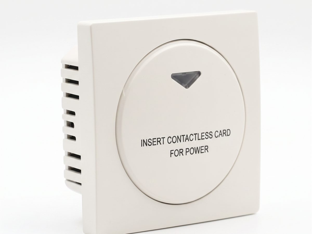
Hotel Key Card Switch — Guest Room Power Control
Hotel key card switch for guest room power control. RFID/IC card detection, insert-and-power, card removal time-delay power-off. 220V AC, 10A-16A, RS485 or dry contact. CE RoHS. OEM/ODM supplier.
This page already points to it as the next recommended reference.
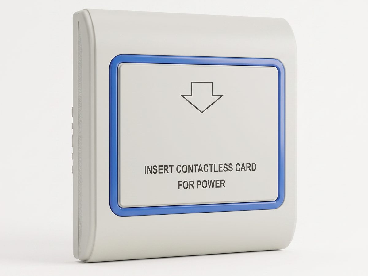
RFID Key Card Switch — Contactless 13.56MHz Guest Room Power Control
RFID key card switch with contactless 13.56MHz detection. Guest simply taps a card on the reader area to power the room, no insertion slot needed. Works alongside hotel door locks. CE RoHS. OEM/ODM supplier.
This page already points to it as the next recommended reference.
Related solutions
3Hotel Room Power Control with Key Card Switches
A practical hotel room power control solution for switching guest-room lighting, air conditioning, and outlets from an authorized room card.
This page already points to it as the next recommended reference.
Guest Room Management System Based on Card-Controlled Power
A practical guest-room management system for controlling room power through key card switches, contactors, and clearly documented operating rules.
It supports the same product context: Hotel Key Card Switch — Guest Room Power Control.
Hotel Energy Saving with Guest-Room Power Switching
A hotel energy-saving solution that uses card-controlled room power to prevent lights, air conditioning, and selected outlets from running unnecessarily.
It supports the same product context: Hotel Key Card Switch — Guest Room Power Control.
Related blog posts
3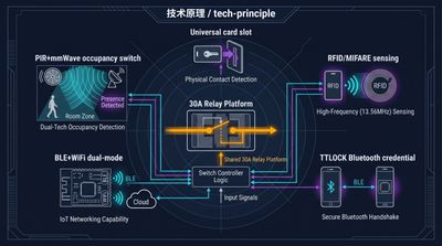
Hotel Key Card Switch: Types, Models, and How to Specify
A hotel key card switch spans universal, RFID, TTLOCK, BLE, and occupancy models. This guide to the key card / keycard switch family covers the head terms —…
It supports the same product context: Hotel Key Card Switch — Guest Room Power Control.
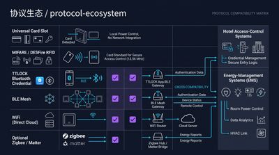
RFID vs NFC for Hotel Key Card Switches: Which Card Tech to Choose
RFID vs NFC for hotel key card switches comes down to range and lock-in: 125kHz / 13.56MHz RFID (MIFARE, Temic) is the hotel standard for room-bound power…
It supports the same product context: Hotel Key Card Switch — Guest Room Power Control.
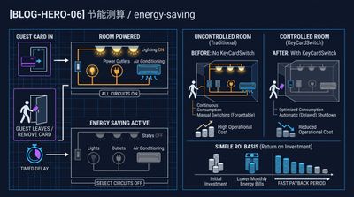
What Is a Hotel Key Card Switch and How It Saves Room Energy
A hotel key card switch is a wall device that powers a guest room when a card is inserted and cuts it when removed, typically saving 25–40% of room…
It supports the same product context: Hotel Key Card Switch — Guest Room Power Control.
Specify your hotel project with our engineers
Send your room count, ceiling type, and protocol preference. We will return a sample plan and quote within 24 business hours.
- Move from general guidance into a product or application discussion.
- Use RFQ when pricing, drawings, MOQ, or launch timing needs structure.
- Keep a direct contact path visible for fast clarifications and handoff.