Hotel Room Power Control System Guide for Engineers
Learn how a hotel room power control system coordinates card switches, distribution boards, lighting, sockets, HVAC, water heaters, relays, and building controls.
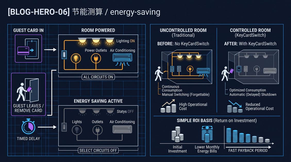
A hotel room power control system is the coordinated electrical architecture that senses room authorization or occupancy, distributes power through correctly selected protective devices, and switches approved loads without compromising life safety or guest convenience. In a typical guest room, a card switch provides a local control signal, while a distribution board, contactors, relays, circuit breakers, and optional communication controllers determine which lighting, socket, HVAC, and water-heater circuits remain energized. The card is not a substitute for a breaker, fire system, or lock; it is one input in a layered control design. Good engineering separates continuously required loads from controllable loads, specifies voltage and current margins, documents neutral and earth continuity, and defines what happens when the card is removed, communication fails, or a guest uses a non-authorized card. This guide explains the architecture, wiring decisions, commissioning method, and deployment choices for new construction and retrofit hotel projects.
Hotel Room Power Control System Guide: What the Architecture Does
A hotel room power control system is an engineered hierarchy connecting a room-entry authorization signal to selected electrical loads through protective and switching equipment. The card switch usually detects a compatible card or token and changes a dry-contact or low-voltage output; it does not directly carry every room load. A local relay or contactor then switches lighting, convenience outlets, fan-coil enable, or a water-heater branch according to the project sequence. The architecture normally divides circuits into always-on, card-controlled, timed, and life-safety categories. It may also expose status through RS485 or another wired bus to a floor controller, building automation system, or room-status network. The essential design facts are load current, inrush current, pole requirements, cable route, protective coordination, emergency-power behavior, and the desired state after card removal. A robust system fails predictably, can be isolated for maintenance, and leaves guests with safe basic services rather than a dark or overheated room.
The card switch is an input, not the whole system
The visible wall device is often called an energy saver switch, key card switch, master switch, or hotel card power switch. Its job is to identify a card presence and produce a control state. Mechanical versions use a slot and microswitch; electronic versions may distinguish authorized RFID or IC cards from unrelated cards. The distinction matters because a hotel wants convenience without creating a false assumption that any plastic card should energize the room.
A card switch output can operate a small relay directly, drive a modular contactor, or report to a room controller. The correct option depends on the load. A wall switch rated for a modest resistive current should not be used as the final switching element for several lighting circuits, socket circuits, or an inductive fan-coil load. The switch rating must be read for the actual load type, not just the headline amperage.
Four functional layers
Engineers can explain a room architecture clearly by separating four layers:
| Layer | Main function | Typical equipment |
|---|---|---|
| Authorization | Detect a card or approved room state | Card switch, reader, door controller |
| Logic | Apply delay, priority, and interlock rules | Relay, room controller, timer module |
| Power switching | Open or close load conductors | Contactor, power relay, SSR where suitable |
| Distribution and protection | Prevent shock, fire, and equipment damage | Main isolator, RCBO, MCB, RCD, SPD, earth bar |
This separation makes troubleshooting easier. If the card is recognized but a lamp stays on, the fault may be in logic or power switching rather than the reader. If the contactor operates but a socket is dead, the distribution branch or protective device should be inspected. Documentation should show every layer and identify which components are accessible to housekeeping, maintenance, and qualified electrical personnel.
State definitions should be written before wiring
A project should define states in plain language before anyone selects a relay. Common states include occupied with card, occupied without card during a grace period, vacant, maintenance, emergency, and communication failure. Each state needs a list of energized and de-energized circuits.
For example, removal of a card may switch decorative lighting immediately, keep a fan-coil enable active for a short delay, and leave a refrigerator outlet permanently energized. A maintenance card may hold all guest circuits active. A fire alarm input may override normal energy logic, but the exact action must follow the building fire strategy and applicable electrical rules. Written state definitions prevent a common commissioning problem in which the installer has correctly wired a device but nobody agrees what “off” means.
Hotel Room Power Control System Guide: Room Distribution and Protection
A hotel room power control system depends on a properly organized room distribution board, because control devices cannot compensate for undersized conductors, poor protective coordination, or an unclear neutral arrangement. The board commonly receives a feeder from the floor distribution panel and divides it into lighting, general sockets, bathroom sockets, HVAC or fan-coil, water heater, minibar or refrigerator, and permanently energized service branches. Each circuit gets a protective device appropriate to its conductor and load. Residual-current protection is especially important in wet areas and wherever local rules require it. The control design should identify which poles are switched, which neutrals remain continuous, where the protective earth terminates, and how a qualified person can isolate each branch. Surge protection, labeling, spare capacity, and thermal space around contactors help the installation remain serviceable throughout the building’s operating life.
Typical circuit groups
The following grouping is a planning model, not a substitute for local electrical design. Actual circuit counts depend on room size, voltage, hotel standard, equipment schedules, and the supply arrangement.
| Circuit group | Normal control treatment | Engineering notes |
|---|---|---|
| Entry and emergency lighting | Often always energized or separately controlled | Never remove required egress illumination through a guest card input |
| Bedroom lighting | Card-controlled or scene-controlled | Consider bedside override and soft-off delay |
| Bathroom lighting and exhaust | Controlled with special sequence | Wet-area protection and fan overrun may be required |
| General sockets | Selectively controlled | Keep refrigerator, network, and medical or accessibility loads separate |
| HVAC enable | Card-controlled with temperature strategy | Fan-coil valve and fan behavior need coordination |
| Water heater | Switched only when approved | Verify recovery time, demand, and contactor duty |
| Minibar or refrigerator | Usually always energized | Compressor inrush can shorten the life of a small relay |
| Door lock, network, and controls | Always energized or backed up | Do not interrupt the room access system accidentally |
The table illustrates why “turn off the room” is an unsafe shorthand. A room contains loads with different operational, thermal, security, and guest-service requirements. Circuit schedules should use equipment names and breaker references rather than labels such as “all power.”
Main isolation and branch protection
A local main isolator lets maintenance personnel disconnect the room board, but it does not replace upstream isolation or safe work procedures. Branch protective devices should be selected from prospective fault current, cable installation method, ambient conditions, and equipment characteristics. A breaker protects conductors; a contactor controls a load. They perform different jobs and should not be treated as interchangeable.
Residual-current devices require careful neutral routing. A switched live that bypasses the sensing device, or a neutral borrowed from another branch, can create nuisance trips or defeat intended protection. Every schematic should show the line, neutral, protective earth, and device terminals. Where a two-pole device is required, both conductors must be selected and wired according to the supply system and applicable code.
Earthing, bonding, and segregation
Control wiring should be segregated from mains conductors when required by the installation rules, especially in shared trunking or a crowded distribution board. Low-voltage signal terminals must not be assumed safe merely because they are small. Terminal blocks should be rated, shrouded where necessary, and labeled.
The protective earth conductor should never be switched by a card device or contactor. Metal enclosures, conduits, and exposed conductive parts require the bonding arrangement specified for the project. If a card switch has a metal faceplate, its bonding method should be resolved during design rather than improvised at handover.
Hotel Room Power Control System Guide: Lighting Circuits and Guest Experience
Lighting is usually the first load group considered in a hotel room power control system because guests immediately notice a poor sequence. A technically correct circuit can still create complaints if bedside reading lights extinguish too quickly, the bathroom fan stops before clearing moisture, or the room becomes dark while a guest is still entering. Designers should combine the card state with local switches, scene controllers, occupancy signals where approved, and time delays. The system should state which lamps are master-controlled and which are local-only. Dimmable drivers and LED power supplies have inrush and leakage characteristics that may differ from incandescent assumptions. Contact ratings should cover the driver manufacturer’s declared load, and test lamps should be representative of the final installation.
Master control versus local switching
A master card state can enable a lighting group while wall switches determine the actual lamp state. Another design uses the card to interrupt the lighting feed and leaves local switches downstream. The first method provides finer control and often better guest experience; the second is simpler but can produce abrupt all-off behavior. A third approach uses a room controller to recall scenes, such as welcome, sleep, and vacancy.
Whichever topology is chosen, the schematic should clarify whether a wall switch is upstream or downstream of the relay. It should also explain the behavior after a card is removed while a local switch remains on. When power is restored, LED drivers may return to their previous state, default on, or default off. Commissioning must test the real driver models rather than relying on assumptions from a sample luminaire.
Delays and overrides
A short exit delay can prevent lights from going dark when a guest removes a card accidentally. A longer delay may keep HVAC enabled while luggage is collected, but it increases the operating time of controlled loads. Delays should be adjustable where the project expects different room types.
Maintenance and housekeeping overrides need controlled access and clear indication. An override may be a service card, a keyed switch, or a controller command. It should not silently defeat protective devices. If an override is held for too long, the system can log or display the condition for staff, but it should not depend on a cloud service for basic room operation.
Hotel Room Power Control System Guide: Sockets, HVAC, and Water Heaters
A hotel room power control system must treat sockets, HVAC, and water heaters as different electrical and operational loads. General-purpose sockets can include guest chargers, hair dryers, irons, and cleaning equipment, so their diversity and fault behavior differ from fixed lighting. HVAC equipment includes motors, valves, contactors, and electronic controls that may require an enable signal instead of raw power interruption. Water heaters combine substantial thermal demand with safety controls and recovery requirements. The card state can be used to request reduced operation, but the final sequence should respect manufacturer instructions, temperature limits, ventilation, and the hotel’s service standard. Keeping selected branches permanently energized is often necessary for refrigeration, communication, access control, and equipment memory. The design goal is controlled operation, not indiscriminate disconnection.
General sockets and permanent outlets
Many projects split socket outlets into controlled and permanent groups. Desk and bedside outlets may be controlled if the operator accepts that a guest charger stops after vacancy. Refrigerator, minibar, router, alarm clock, and accessibility equipment outlets commonly remain live. A room schedule should identify permanent outlets by location and purpose so housekeeping does not assume a dead socket is a fault.
The switched socket circuit needs an inrush assessment if it supplies chargers, televisions, or power strips. A contactor that is comfortably rated for steady current may still experience wear from repeated switching of capacitive electronic loads. Contactors with suitable utilization categories, suppression, and an adequate mechanical life are part of the specification.
HVAC enable logic
Fan-coil units often have a manufacturer-provided enable input, occupancy input, or thermostat interface. Using that interface can be preferable to cutting the unit’s complete supply, particularly where the controller needs to preserve valve position, frost protection, or fault reporting. If the project does switch HVAC power, the relay and contactor must be rated for the motor and control circuit.
A card switch should not be the sole authority for comfort control. Room temperature, window contacts, door status, and central plant constraints may also matter. An unoccupied state can request a setback temperature rather than immediate shutdown. The exact sequence belongs in the controls narrative and must be tested across cooling, heating, fan-only, and alarm states.
Water-heater switching
Water heaters can create a substantial load and may have high inrush or resistive current at the upper end of a room circuit. Use a properly rated contactor with a coil voltage that matches the control architecture. A card signal should normally command the contactor, not carry the heater current through a small wall device.
The design should answer whether hot water is available immediately at check-in, how long recovery takes after vacancy, and whether a local thermostat or safety cut-out remains active. The heater branch may be better controlled by a dedicated schedule or plant strategy than by every card removal. Never bypass thermal cut-outs, over-temperature protection, or equipment isolation while attempting to improve energy behavior.
Hotel Room Power Control System Guide: Relays, Contactors, and Switching Methods
Relays and contactors are the power-switching layer of a hotel room power control system. A relay is commonly used for lower-power control or signaling, while a contactor is designed for frequent switching of higher current and motor-related loads. The selection depends on voltage, steady current, inrush, utilization category, number of poles, coil type, enclosure temperature, noise, and expected switching cycles. A normally open contact produces an energized-on behavior; a normally closed contact produces a different failure mode and should be chosen intentionally. Coil suppression can reduce electrical noise but may change drop-out time. Interposing relays can protect a controller output, provide voltage isolation, or convert a low-voltage signal into a compatible coil command.
Choosing a contactor
The nameplate current is only one selection parameter. Engineers should review:
| Parameter | Question to answer |
|---|---|
| Load voltage | Is the device suitable for the room supply and frequency? |
| Load type | Resistive heater, LED driver, motor, transformer, or mixed load? |
| Utilization category | Does the duty match the switching application? |
| Poles | Are one, two, or more conductors intended to open? |
| Coil voltage | AC or DC, and compatible with the control output? |
| Inrush | What happens at lamp, compressor, or transformer startup? |
| Endurance | How many operations are expected over the service life? |
| Heat and noise | Will board temperature or audible hum affect the room? |
| Terminal capacity | Can the specified conductor sizes be terminated safely? |
Oversizing is not a cure for every issue, but generous electrical and thermal margins usually help. The component must still fit the enclosure, meet the project’s switching requirements, and be accessible for replacement.
Coil behavior and suppression
AC coils can create transients when opened. Suppression devices may reduce interference to card readers and communication equipment. DC coils often use diode or dedicated suppressor arrangements, but polarity matters. A diode applied to an AC coil is incorrect. Suppression can also slow release, so a project that needs a contactor to drop quickly should validate the actual timing.
Coil voltage should be separated from load voltage in drawings and labels. A technician should be able to see whether a 24 V control circuit is commanding a 230 V load without tracing every wire. Test points, status LEDs, and an accessible manual test method can reduce commissioning time.
Fail-safe and fail-operational choices
There is no universal “fail-safe” state for every guest-room load. Turning lights on during a controller fault may improve safety but increase nuisance operation. Dropping HVAC may protect energy use but create temperature complaints. Door access and emergency equipment have their own rules. The project team should define the desired state per circuit and select normally open or normally closed contacts accordingly.
A documented failure matrix should include loss of card, welded contact, open coil, tripped breaker, controller reset, communication loss, and restoration after a power outage. The matrix belongs in commissioning records, not only in a design meeting note.
Hotel Room Power Control System Guide: RS485 and Wired Coordination
RS485 can extend a hotel room power control system from an isolated card switch into a coordinated network of room controllers, floor gateways, and building automation interfaces. RS485 is an electrical physical layer, not a complete application protocol; the project must define addressing, baud rate, parity, termination, biasing, message format, timeout, and ownership of each command. Common industrial protocols may be used when supported by all devices, but a named protocol on a product sheet does not guarantee interoperability. The bus should be routed as a suitable pair with polarity maintained, shields handled according to the electrical design, and termination applied at the ends of the trunk rather than every device. Networked control should add visibility and coordination while preserving a predictable local fallback when the bus, controller, or supervisory system is unavailable.
Bus topology and wiring
A daisy-chain trunk is generally easier to control than a star made from long uncoordinated branches. Cable selection depends on distance, noise environment, baud rate, and manufacturer guidance. Keep the pair away from high-current switching conductors where practical, and cross power cables at appropriate angles if they must intersect. Every device should have a unique address.
Termination resistors belong at the physical ends of the line, not automatically at every card switch. Biasing should be provided by the defined network design. Shield grounding needs one clear rule, because random grounding at many points can create unwanted current paths. Record cable routes and spare pairs for future maintenance.
What to exchange over RS485
A useful room message set can include card-present state, room mode, controller health, contactor feedback, door state, window state, temperature, manual override, and fault codes. Commands may include set mode, request setback, release override, and acknowledge fault. The system should distinguish a command received from a physical output confirmed. A controller may accept “lights off” while a welded contact means the actual load remains on.
Polling intervals and timeouts should be selected so a temporary communication issue does not cause rapid relay chatter. A stale-state timer can move a room into a defined fallback mode. The timeout should be visible to maintenance staff and included in test scripts.
Local fallback
A networked room should continue to provide a reasonable local experience when the floor controller is offline. The card switch may still operate the local relay, or the room controller may retain the last safe schedule. The fallback should not permit a supervisory command to override required protections. After communication returns, the reconciliation rule must be defined: local state may win, central state may win, or the system may require an explicit reset.
Hotel Room Power Control System Guide: BAS and Room-Status Integration
Integration with a building automation system can make a hotel room power control system part of a broader operational sequence, but the integration boundary must be explicit. The room system may publish occupancy-related status, equipment availability, temperature, alarms, and override state; the building system may provide plant availability, schedules, demand limits, or operating mode. A guest room should not depend on an internet connection or a proprietary cloud service for basic local switching. Interfaces should use documented points, stable naming, read-only versus command permissions, and a clear priority order. The controls narrative should state what occurs during BAS maintenance, gateway failure, controller reboot, network segmentation, and emergency operation. Integration is valuable when it reduces ambiguity and duplicated logic, not when it hides a simple local circuit behind an opaque dependency.
Point lists and command authority
Create an interface point list before procurement. It should identify point name, data type, direction, normal state, update interval, alarm treatment, and command authority. For example, “room occupied” may be a status from the local card controller, while “HVAC enable request” may be a command from the room logic to a fan-coil interface.
Avoid two systems commanding the same relay without a priority rule. If the card switch, room controller, BAS, and fire interface all have a path to a contactor, the design needs a clear arbitration method. Hardwired priority inputs may be appropriate for specific functions. Software priority alone should not be assumed to cover every safety requirement.
Room status and housekeeping
A room power system can expose useful operational states such as guest card present, vacancy timer active, service override, window open, and equipment fault. These states may support housekeeping coordination, but the privacy and access policy belongs to the hotel operator. The system should avoid claiming a person is absent solely because a card is removed; a guest may be inside without leaving a card in the holder.
Status values should be named consistently across floor and central systems. A commissioning team can then compare the physical room, controller display, and BAS graphic without translating ambiguous abbreviations.
Hotel Room Power Control System Guide: New Construction Deployment
A new-build hotel offers the cleanest opportunity to implement a hotel room power control system because feeders, containment, room boards, and control cabling can be coordinated before walls close. The design team can reserve distribution-board space for contactors, route RS485 trunks, separate permanent and switched outlets, and place card switches at the intended entry point. Procurement should lock the electrical schedules, card technology, coil voltages, and interface protocol before bulk production. A room mock-up is strongly recommended. It reveals problems such as noisy contactors, insufficient board space, inconvenient isolation, conflicting furniture, card-switch height, and an HVAC interface that was assumed but not supplied. New construction should still plan for maintenance, replacement, and future circuit expansion rather than filling every enclosure to its physical limit.
New-build sequence
- Confirm room electrical loads, supply system, local requirements, and equipment schedules.
- Divide loads into permanent, controlled, timed, and priority categories.
- Write the state and failure matrix before finalizing schematics.
- Select contactors, relays, protective devices, enclosures, and signal interfaces.
- Coordinate architectural locations, furniture, doors, and card-switch access.
- Build and review a representative room mock-up.
- Test the card, local switches, HVAC, sockets, water heater, and BAS points together.
- Issue installation drawings with terminal numbers and cable schedules.
- Commission sample rooms before repeating the installation across the floor.
- Record as-built changes and train operations staff.
This sequence reduces the risk of discovering at handover that the card switch is mounted where luggage blocks it or that the contactor enclosure cannot dissipate heat.
Coordination with other trades
Electrical, HVAC, door-access, interior, fire, and IT teams all touch the room sequence. A card switch may be purchased by one contractor, installed by another, and integrated by a controls specialist. The interface responsibility matrix should identify who supplies power, who terminates signals, who programs delays, who tests contact feedback, and who signs off each function.
Cable containment and penetration details deserve early attention. A control bus routed through a wet area, a shared neutral between separate protective devices, or an unsealed wall box can create defects that are expensive to correct after finishes are complete.
Hotel Room Power Control System Guide: Retrofit Deployment
A retrofit hotel has a different risk profile because existing wiring, room boards, guest operations, and undocumented modifications may be discovered only after work begins. A retrofit hotel room power control system should start with a survey, not a product order. Record supply voltage, breaker types, conductor sizes, neutral arrangement, earth continuity, available enclosure space, circuit destinations, HVAC interface, and existing access-control signals. Identify rooms with unusual equipment, accessibility adaptations, medical needs, or owner-installed appliances. Decide whether the project can add a new controller and contactor board, replace the card switch only, or reorganize circuits during planned room renovation. Temporary isolation, guest-room scheduling, dust control, and post-work testing are part of the engineering plan. A retrofit that preserves unknown hazards behind a new decorative plate is not a successful modernization.
Retrofit survey checklist
The survey team should photograph the board and room entry location, trace each branch, and compare labels with actual behavior. Use approved test procedures and qualified personnel. Record:
| Survey item | Why it matters |
|---|---|
| Supply voltage and phases | Determines device and contactor selection |
| Main and branch protection | Reveals capacity and protection gaps |
| Neutral and earth arrangement | Prevents incorrect switching and nuisance trips |
| Circuit destinations | Separates permanent from controllable loads |
| Board dimensions and heat | Confirms physical retrofit capacity |
| Existing control voltage | Avoids coil and interface mismatch |
| HVAC terminals | Determines enable versus power switching |
| Card technology | Confirms compatibility and authorization behavior |
| Network route | Shows whether RS485 can be added reliably |
| Room operating schedule | Supports phased isolation planning |
Do not infer circuit function from labels alone. Test and verify the actual conductor route.
Choosing a retrofit strategy
A minimally invasive strategy may retain the existing board and add a correctly enclosed contactor module for selected circuits. This can reduce wall disruption but may leave limited space and complicated maintenance. A board replacement can produce cleaner labeling and protection but requires more shutdown time and careful coordination with every branch.
Some rooms may need different strategies because of legacy HVAC, split supplies, or later-added appliances. Standardization is useful, but forcing every room into one wiring pattern can create hidden compromises. Document exceptions and keep spare parts compatible with the installed population.
Phased installation and handover
Retrofits are often installed by floor or room batch. A pilot room should remain available for training and repeatability checks. Before a room returns to service, test card removal, authorized and non-authorized cards, local lighting, permanent outlets, controlled outlets, HVAC, bathroom equipment, water heater sequence where applicable, protective devices, and any communication points.
Leave a temporary status label during the pilot phase so staff know which rooms have the new sequence. Final handover should include as-built drawings, terminal schedules, device manuals, spare components, test results, and a clear process for reporting a nuisance trip or failed contactor.
Hotel Room Power Control System Guide: Commissioning and Fault Finding
Commissioning a hotel room power control system proves that the installed architecture matches the design narrative under normal, abnormal, and recovery conditions. Start with visual inspection and de-energized continuity checks performed by qualified personnel, then energize in a controlled sequence. Verify protective-device labeling, terminal torque records where required, conductor identification, enclosure covers, and separation of control and mains wiring. Test every circuit with representative loads, not only a small lamp. Remove an authorized card, insert it again, present an unrelated card, trigger each local switch, trip and reset the relevant protective device, interrupt communication, reboot the controller, and restore supply power. Record measured behavior and timing. A room is not commissioned when the contactor clicks; it is commissioned when the guest experience, electrical protection, control logic, and maintenance response all agree.
Functional test matrix
| Test | Expected result | Evidence to record |
|---|---|---|
| Insert authorized card | Defined guest state begins | Card type, time, room state |
| Remove card | Each circuit follows its delay and priority | Measured delay and load result |
| Insert unrelated card | Result follows authorization policy | Card behavior and indication |
| Operate local switch | Local control remains available as designed | Lamp or device response |
| Open window or door input | HVAC sequence follows narrative | Temperature/control state |
| Lose RS485 link | Local fallback occurs without chatter | Timeout and recovery time |
| Trip branch protection | Fault is isolated and visible | Device reference and reset result |
| Restore supply | Outputs return to defined state | Startup state and alarms |
| Activate service override | Only permitted circuits change | Override indication and release |
| Check feedback | Command and physical state agree | Contact and controller status |
The completed matrix should identify the person, date, instrument, and room or panel reference.
Troubleshooting by layer
If the card switch indicator changes but no contactor operates, check the control voltage, fuse, output relay, coil wiring, and interlock. If the contactor operates but the load remains off, inspect the protective device, line terminals, pole continuity, downstream neutral, and load itself. If the load stays on after a command to open, check welded contacts, bypass conductors, a parallel feed, and an incorrect normally closed terminal.
If RS485 status is intermittent, inspect polarity, termination, address duplication, shield treatment, cable damage, and electrical noise from nearby switching. If an RCD trips, do not repeatedly reset it as a workaround. Isolate branches using an approved procedure and investigate insulation, neutral mixing, equipment leakage, and wiring errors.
Hotel Room Power Control System Guide: Safety, Documentation, and Maintenance
Safety in a hotel room power control system comes from layered design, competent installation, protective devices, clear isolation, and disciplined maintenance. A card switch must never be presented as a safety isolation device. Staff need to know which controls they may operate and which tasks require qualified electrical personnel. Drawings should show the single-line diagram, wiring diagram, terminal schedule, circuit schedule, device ratings, control voltage, communication topology, address map, and state matrix. Maintenance plans should include contactor inspection, terminal checks, relay replacement criteria, card-switch cleaning, communication diagnostics, and review of nuisance trips. Keep spare parts identified by installed specification, not only by appearance. If a product is replaced, verify coil voltage, pole arrangement, ratings, dimensions, and terminal layout. Change control matters because a small substitution can alter inrush performance or the intended failure state.
Labeling and isolation
Every distribution board should have durable labels that correspond to the drawings. Labels such as “room power” are too broad for fault finding. Use circuit numbers, load names, contactor references, and control source. A maintenance person should be able to isolate the water-heater branch without guessing which of three similar breakers is correct.
Isolation points should be accessible without moving guest furniture where practical. Where a controller has a manual override, label its normal position and explain when it may be used. Emergency procedures should be consistent with the building’s electrical and fire plans.
Maintenance records
Record device model, installation date, room, circuit duty, and replacement history. A repeated contactor failure may indicate inrush, a loose terminal, excessive switching frequency, heat, or an unsuitable utilization category. A repeated card-switch complaint may be caused by mounting, card compatibility, or a sequence that guests do not understand.
Review trends without claiming a guaranteed energy percentage. The useful questions are whether the intended circuits respond, whether vacancy states are reached, whether equipment remains available, and whether faults are found before guests report them.
Hotel Room Power Control System Guide: Design Decisions and Procurement
Procurement for a hotel room power control system should be based on an approved performance specification rather than a photograph of a wall switch. The specification should state supply conditions, card technology, authorized-card behavior, output type, contact ratings, control voltage, number of poles, mounting method, enclosure requirements, communication interface, environmental conditions, labeling, spare-parts expectations, and test documentation. Ask suppliers to show how the proposed device fits the room sequence, not only how it looks in a catalog. Confirm whether the wall product is a sensor, a relay, or a controller, and identify the actual component that carries each load. A low purchase price can be outweighed by board modifications, incompatible cards, difficult servicing, or premature contact wear. Samples should be tested with final luminaires, HVAC interfaces, and representative guest loads before volume approval.
Practical specification questions
| Question | Required project answer |
|---|---|
| What does the card switch detect? | Authorized card, any card, token, or dry contact |
| What is its output? | Dry contact, powered output, bus message, or relay |
| Which component switches the load? | Internal relay, modular relay, or contactor |
| Which loads are permanent? | Refrigerator, network, lock, emergency, and other exceptions |
| How are HVAC commands handled? | Enable input, thermostat logic, or supply switching |
| What happens during communication loss? | Defined local fallback and timeout |
| What is the reset state? | Output state after power and controller restart |
| How is maintenance override controlled? | Service card, keyed input, or authorized command |
| How are drawings and addresses delivered? | As-built package, point list, and room map |
| What spares are held? | Switches, relays, contactors, fuses, and terminal parts |
These questions expose architectural gaps early, when they are inexpensive to correct.
Avoiding misleading product comparisons
Comparing card switches by rated current alone can lead to a poor decision. Two products may both show a similar current but differ in load category, pole count, card recognition, noise, terminal capacity, or output architecture. A switch designed to command a contactor is not equivalent to one intended to carry a socket circuit directly.
A fair comparison uses the complete chain: input behavior, control output, power-switching device, protective arrangement, communication, installation method, commissioning tools, and lifecycle support. Include the cost and time of panel work, not only the faceplate price.
Hotel Room Power Control System Guide: A Repeatable Engineering Workflow
A repeatable workflow turns a hotel room power control system from a collection of devices into a verifiable building subsystem. First, establish the room load schedule and classify circuits. Second, write normal states, overrides, and failure behavior. Third, draw the single-line and control schematics together so the signal path and power path can be reviewed in one meeting. Fourth, select switching devices based on real load duty and expected operation. Fifth, coordinate HVAC, access, fire, interior, and network interfaces. Sixth, test a mock-up or pilot room. Seventh, install with traceable labeling and cable records. Eighth, commission using a matrix that covers normal use, abnormal events, and recovery. Finally, hand over drawings, settings, spare parts, and maintenance instructions. This workflow is deliberately conservative: it treats the visible card switch as one component in a documented electrical system and makes every assumption available for review before guest occupancy.
Step 1: classify every load
List each circuit by breaker, conductor, destination, supply, and operating priority. Mark whether the card state controls it, requests a mode change, or has no authority over it. Include hidden loads such as exhaust fans, valve actuators, network equipment, door controllers, and minibar sockets.
Step 2: define authority and timing
Write who can command each state and how long transitions take. Include local wall controls, card inputs, service overrides, window contacts, BAS commands, and emergency inputs. If two commands conflict, state which has priority.
Step 3: verify the physical path
Trace the signal from card to input, logic, coil, contact, breaker, conductor, and load. Draw terminal numbers and identify test points. A schematic that omits the neutral or feedback path is incomplete for commissioning.
Step 4: test reality, then update drawings
Use representative hardware and loads. Record deviations as they happen instead of relying on memory at handover. The final drawing should describe the room that exists, including exceptions and replacement part numbers.
Hotel Room Power Control System Guide: Common Design Mistakes
The most common mistakes in a hotel room power control system are architectural rather than cosmetic. Designers sometimes switch every circuit, including refrigerator and access-control outlets, because the brief says “energy saving.” Installers sometimes connect a large inductive or electronic load directly to a small card-switch contact. Controls teams sometimes assume an RS485 label means plug-and-play interoperability. Retrofit teams sometimes reuse an undocumented neutral or place new equipment in a board with no thermal or spare capacity. Operators may receive no explanation of service override or reset behavior. Each mistake can be prevented by a load classification, a complete schematic, a point list, and a witnessed pilot-room test. The project should also avoid promising a particular energy outcome without measured operating data. The responsible claim is that the architecture controls defined loads according to defined states; actual results depend on schedules, guest behavior, equipment, climate, and commissioning quality.
Mistake: switching protective or essential functions
A master relay should not interrupt protective earth. Required emergency or life-safety functions need their own design and authority. A convenience sequence must not silently override those functions.
Mistake: ignoring inrush and duty
LED drivers, compressors, transformers, and motors can stress contacts even when steady current appears modest. Ask for manufacturer data and test the installed combination. Consider switching frequency, suppression, and contact feedback.
Mistake: leaving no local fallback
A room that becomes unusable when a gateway fails is overdependent on its network. Keep a defined local behavior and make the failure visible to staff.
Mistake: treating card removal as proof of vacancy
Guests may leave a card on a table, use a second card, or remain in the room without the card. Card control is an operational proxy, not a complete occupancy measurement. The sequence should be comfortable and transparent.
Hotel Room Power Control System Guide: Final Review Checklist
Before approving a hotel room power control system, review the design from four perspectives: electrical safety, guest operation, controls behavior, and maintainability. Confirm that every switched circuit has an identified switching device and protective path. Confirm that permanent circuits are not accidentally tied to the master output. Confirm the card switch is compatible with the intended cards and produces the documented signal. Confirm contactors are rated for actual loads and coil voltage. Confirm RS485 topology, addresses, termination, and fallback. Confirm BAS points and command priority. Confirm new-build or retrofit access, labels, spares, and training. Finally, witness the sequence in a representative room with real lamps, sockets, HVAC, and water-heater controls where those loads are included. A signed checklist is more valuable than a generic statement that the system was tested because it preserves exactly what was tested and what remains outside scope.
Approval questions
- Does the single-line diagram match the installed distribution board?
- Are line, neutral, earth, control, and communication conductors clearly identified?
- Are always-on and card-controlled circuits separated and labeled?
- Is every relay or contactor suitable for its real load and switching duty?
- What happens after card removal, controller reset, bus failure, and power restoration?
- Can maintenance staff isolate and replace a component safely?
- Does the retrofit strategy account for undocumented circuits and guest scheduling?
- Are BAS commands, local controls, and emergency inputs assigned clear priorities?
- Are drawings, addresses, settings, test results, and spare parts included in handover?
Closing perspective
The best room power architecture is understandable at the wall, in the distribution board, and on the controls network. It gives guests convenient local operation, gives operators useful status, and gives engineers a traceable path from a card event to each approved load. It separates control from protection, treats different loads according to their electrical behavior, and makes failure states deliberate rather than accidental. Whether the project is a new hotel or a retrofit, the fundamentals remain the same: classify circuits, define states, select switching devices correctly, coordinate interfaces, test the real room, and document the result. A card switch can be a simple and effective part of that architecture when its role is specified honestly and integrated with the rest of the electrical system.
Part of this article content is generated by AI and optimized for professional accuracy and readability.
Not sure which sensor fits your project?
Talk to our mmWave application engineers for a free consultation.
Find the right presence sensor for your hotel project
Compare the 3 protocols, check hotel-specific case studies, and download the installation guide
Related products
2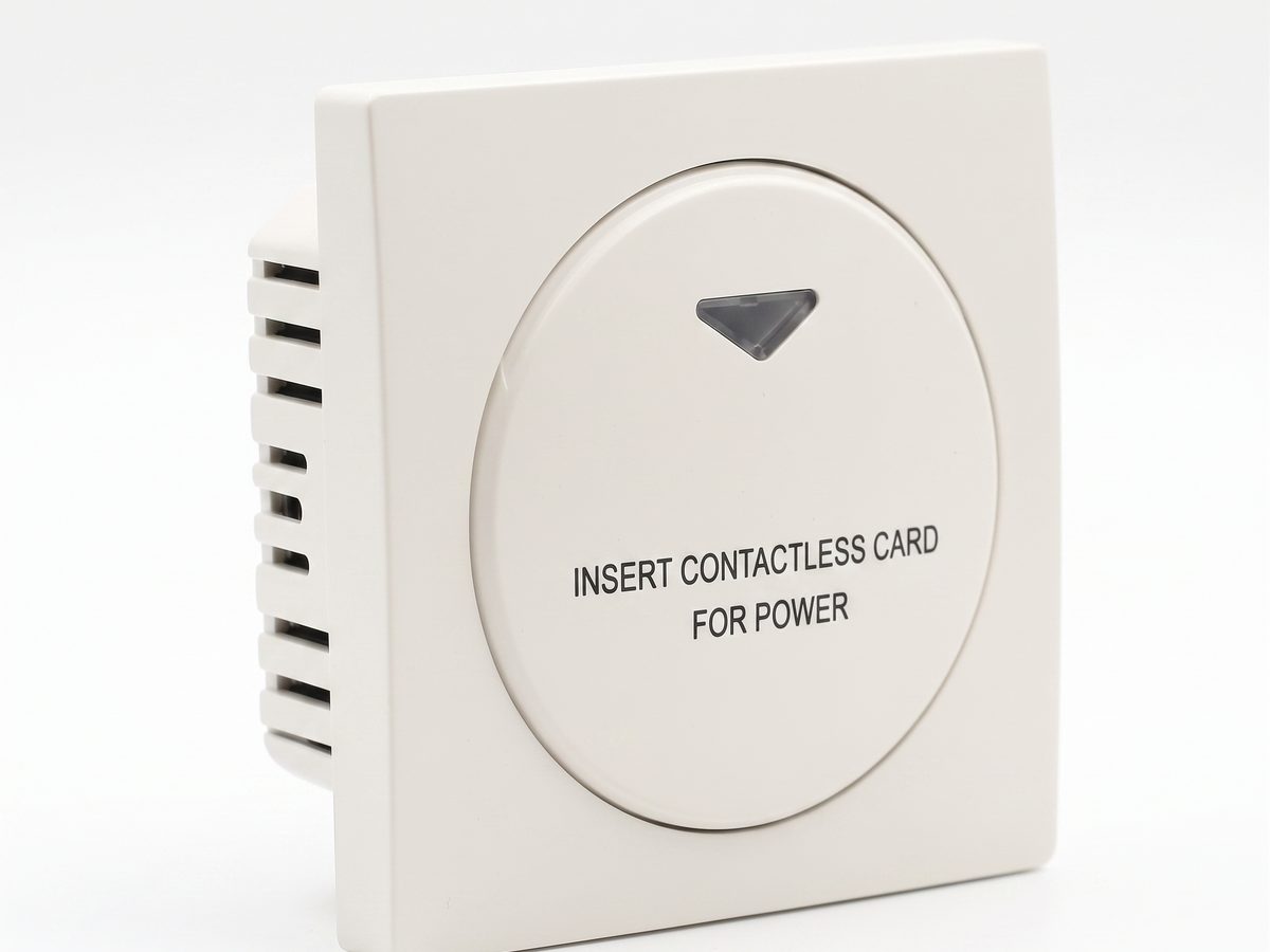
Hotel Key Card Switch — Guest Room Power Control
Hotel key card switch for guest room power control. RFID/IC card detection, insert-and-power, card removal time-delay power-off. 220V AC, 10A-16A, RS485 or dry contact. CE RoHS. OEM/ODM supplier.
This page already points to it as the next recommended reference.
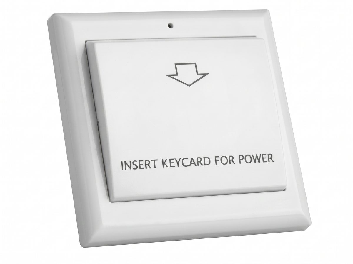
Key Card Switch Accessories — Face Plates, 86 Boxes, Contactors and Power
Key card switch accessories for the 86 box install: face plates, 86 box mounting bases, contactors for high-load HVAC, power supplies, and RS485 hubs. Choose accessories to complete any 86 box key card switch project.
This page already points to it as the next recommended reference.
Related solutions
3Hotel Room Power Control with Key Card Switches
A practical hotel room power control solution for switching guest-room lighting, air conditioning, and outlets from an authorized room card.
This page already points to it as the next recommended reference.
Guest Room Management System Based on Card-Controlled Power
A practical guest-room management system for controlling room power through key card switches, contactors, and clearly documented operating rules.
It supports the same product context: Hotel Key Card Switch — Guest Room Power Control.
Hotel Energy Saving with Guest-Room Power Switching
A hotel energy-saving solution that uses card-controlled room power to prevent lights, air conditioning, and selected outlets from running unnecessarily.
It supports the same product context: Hotel Key Card Switch — Guest Room Power Control.
Related blog posts
3
Hotel Key Card Switch: Types, Models, and How to Specify
A hotel key card switch spans universal, RFID, TTLOCK, BLE, and occupancy models. This guide to the key card / keycard switch family covers the head terms —…
It supports the same product context: Hotel Key Card Switch — Guest Room Power Control.
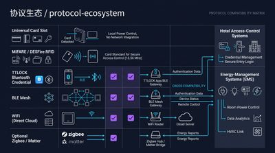
RFID vs NFC for Hotel Key Card Switches: Which Card Tech to Choose
RFID vs NFC for hotel key card switches comes down to range and lock-in: 125kHz / 13.56MHz RFID (MIFARE, Temic) is the hotel standard for room-bound power…
It supports the same product context: Hotel Key Card Switch — Guest Room Power Control.
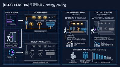
What Is a Hotel Key Card Switch and How It Saves Room Energy
A hotel key card switch is a wall device that powers a guest room when a card is inserted and cuts it when removed, typically saving 25–40% of room…
It supports the same product context: Hotel Key Card Switch — Guest Room Power Control.
Specify your hotel project with our engineers
Send your room count, ceiling type, and protocol preference. We will return a sample plan and quote within 24 business hours.
- Move from general guidance into a product or application discussion.
- Use RFQ when pricing, drawings, MOQ, or launch timing needs structure.
- Keep a direct contact path visible for fast clarifications and handoff.