دليل نظام التحكم في طاقة غرف الفندق للمهندسين
تعرف على كيفية تنسيق نظام التحكم في طاقة غرف الفندق لمفاتيح البطاقات، ولوحات التوزيع، والإضاءة، والمقابس، وأنظمة التدفئة والتهوية وتكييف الهواء، وسخانات المياه، والمرحلات، وأنظمة التحكم في المباني.
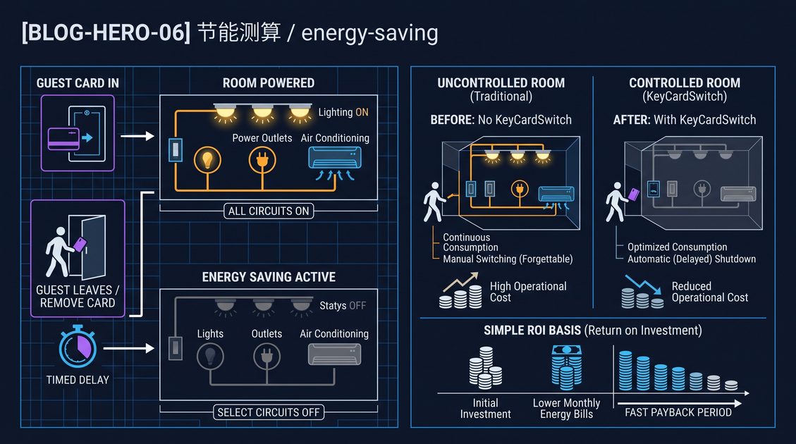
نظام التحكم في طاقة غرف الفندق هو هندسة كهربائية منسقة تستشعر تفويض الغرفة أو إشغالها، وتوزع الطاقة عبر أجهزة الحماية المختارة بشكل صحيح، وتتحكم في الأحمال المعتمدة دون المساس بسلامة الحياة أو راحة الضيوف. في غرفة ضيوف نموذجية، يوفر مفتاح البطاقة إشارة تحكم محلية، بينما تحدد لوحة التوزيع، والموصلات، والمرحلات، وقواطع الدوائر، ووحدات التحكم في الاتصالات الاختيارية دوائر الإضاءة، والمقابس، وأنظمة التدفئة والتهوية وتكييف الهواء، وسخانات المياه التي تظل مفعلة. البطاقة ليست بديلاً عن قاطع الدائرة، أو نظام الحريق، أو القفل؛ إنها مدخل واحد في تصميم تحكم متعدد الطبقات. يفصل التصميم الجيد الأحمال المطلوبة باستمرار عن الأحمال القابلة للتحكم، ويحدد هوامش الجهد والتيار، ويوثق استمرارية المحايد والأرض، ويعرف ما يحدث عند إزالة البطاقة، أو فشل الاتصال، أو استخدام ضيف لبطاقة غير مصرح بها. يشرح هذا الدليل الهندسة، وقرارات الأسلاك، وطريقة التشغيل، وخيارات النشر لمشاريع الفنادق الجديدة والتجديد.
دليل نظام التحكم في طاقة غرف الفندق: ما تفعله الهندسة
نظام التحكم في طاقة غرف الفندق هو تسلسل هرمي مصمم يربط إشارة تفويض دخول الغرفة بالأحمال الكهربائية المختارة عبر معدات الحماية والتحكم. يكتشف مفتاح البطاقة عادةً بطاقة أو رمزاً متوافقاً ويغير مخرجاً جافاً أو منخفض الجهد؛ إنه لا يحمل مباشرة كل أحمال الغرفة. ثم يقوم مرحلي أو موصل محلي بتشغيل الإضاءة، ومقابس الراحة، وتمكين ملف المروحة، أو فرع سخان المياه وفقاً لتسلسل المشروع. تقسم الهندسة عادةً الدوائر إلى فئات دائمة التشغيل، ومتحكم بها بالبطاقة، ومؤقتة، وسلامة الحياة. قد تعرض أيضاً الحالة عبر RS485 أو ناقل سلكي آخر إلى وحدة تحكم في الطابق، أو نظام أتمتة المباني، أو شبكة حالة الغرفة. حقائق التصميم الأساسية هي تيار الحمل، وتيار التدفق، ومتطلبات الأقطاب، ومسار الكابل، وتنسيق الحماية، وسلوك طاقة الطوارئ، والحالة المرغوبة بعد إزالة البطاقة. يفشل النظام القوي بشكل متوقع، ويمكن عزله للصيانة، ويترك الضيوف مع خدمات أساسية آمنة بدلاً من غرفة مظلمة أو محمومة.
مفتاح البطاقة هو مدخل، وليس النظام بأكمله
يُطلق على جهاز الحائط المرئي غالباً اسم مفتاح توفير الطاقة، أو مفتاح بطاقة المفتاح، أو المفتاح الرئيسي، أو مفتاح طاقة بطاقة الفندق. مهمته هي تحديد وجود بطاقة وإنتاج حالة تحكم. تستخدم الإصدارات الميكانيكية فتحة ومفتاحاً دقيقاً؛ قد تميز الإصدارات الإلكترونية بين بطاقات RFID أو IC المصرح بها والبطاقات غير ذات الصلة. التمييز مهم لأن الفندق يريد الراحة دون خلق افتراض خاطئ بأن أي بطاقة بلاستيكية يجب أن تشغل الغرفة.
يمكن لمخرج مفتاح البطاقة تشغيل مرحلي صغير مباشرة، أو قيادة موصل معياري، أو الإبلاغ إلى وحدة تحكم الغرفة. يعتمد الخيار الصحيح على الحمل. لا ينبغي استخدام مفتاح حائط مصنف لتيار مقاوم متواضع كعنصر تحكم نهائي لعدة دوائر إضاءة، أو دوائر مقابس، أو حمل ملف مروحة حثي. يجب قراءة تصنيف المفتاح لنوع الحمل الفعلي، وليس فقط الأمبير الرئيسي.
أربع طبقات وظيفية
يمكن للمهندسين شرح هندسة الغرفة بوضوح عن طريق فصل أربع طبقات:
| الطبقة | الوظيفة الرئيسية | المعدات النموذجية |
|---|---|---|
| التفويض | اكتشاف بطاقة أو حالة غرفة معتمدة | مفتاح بطاقة، قارئ، وحدة تحكم الباب |
| المنطق | تطبيق التأخير، والأولوية، وقواعد التعشيق | مرحلي، وحدة تحكم الغرفة، وحدة مؤقت |
| تبديل الطاقة | فتح أو إغلاق موصلات الحمل | موصل، مرحلي طاقة، SSR حيثما يناسب |
| التوزيع والحماية | منع الصدمات، والحرائق، وتلف المعدات | عازل رئيسي، RCBO، MCB، RCD، SPD، شريط أرضي |
يجعل هذا الفصل استكشاف الأخطاء أسهل. إذا تم التعرف على البطاقة لكن المصباح يظل مضاءً، فقد يكون العطل في المنطق أو تبديل الطاقة وليس في القارئ. إذا عمل الموصل لكن المقبس ميت، فيجب فحص فرع التوزيع أو جهاز الحماية. يجب أن توضح الوثائق كل طبقة وتحدد المكونات التي يمكن الوصول إليها من قبل التدبير المنزلي، والصيانة، والأفراد الكهربائيين المؤهلين.
يجب كتابة تعريفات الحالة قبل الأسلاك
يجب أن يحدد المشروع الحالات بلغة واضحة قبل أن يختار أي شخص مرحلياً. تشمل الحالات الشائعة: مشغولة مع بطاقة، مشغولة بدون بطاقة خلال فترة سماح، شاغرة، صيانة، طوارئ، وفشل الاتصال. تحتاج كل حالة إلى قائمة بالدوائر المفعلة وغير المفعلة.
على سبيل المثال، قد يؤدي إزالة البطاقة إلى إيقاف الإضاءة الزخرفية فوراً، وإبقاء تمكين ملف المروحة نشطاً لتأخير قصير، وإبقاء مقبس الثلاجة مفعلاً بشكل دائم. قد تبقي بطاقة الصيانة جميع دوائر الضيوف نشطة. قد يتجاوز إدخال إنذار الحريق منطق الطاقة العادي، لكن الإجراء الدقيق يجب أن يتبع استراتيجية حريق المبنى والقواعد الكهربائية المعمول بها. تمنع تعريفات الحالة المكتوبة مشكلة تشغيل شائعة حيث يكون المثبت قد سلك جهازاً بشكل صحيح لكن لا أحد يتفق على معنى "إيقاف".
دليل نظام التحكم في طاقة غرف الفندق: توزيع الغرفة وحمايتها
يعتمد نظام التحكم في طاقة غرف الفندق على لوحة توزيع غرفة منظمة بشكل صحيح، لأن أجهزة التحكم لا يمكنها تعويض الموصلات صغيرة الحجم، أو تنسيق الحماية الضعيف، أو ترتيب المحايد غير الواضح. تستقبل اللوحة عادةً مغذياً من لوحة توزيع الطابق وتقسمه إلى إضاءة، ومقابس عامة، ومقابس حمام، وأنظمة التدفئة والتهوية وتكييف الهواء أو ملف المروحة، وسخان المياه، والميني بار أو الثلاجة، وفروع الخدمة الدائمة التشغيل. تحصل كل دائرة على جهاز حماية مناسب لموصلها وحملها. حماية التيار المتبقي مهمة بشكل خاص في المناطق الرطبة وفي أي مكان تتطلبه القواعد المحلية. يجب أن يحدد تصميم التحكم الأقطاب التي يتم تبديلها، والمحايدات التي تظل مستمرة، وأين ينتهي سلك الحماية، وكيف يمكن لشخص مؤهل عزل كل فرع. تساعد حماية الطفرة، والوسم، والقدرة الاحتياطية، والمساحة الحرارية حول الموصلات في بقاء التركيب قابلاً للخدمة طوال عمر المبنى التشغيلي.
مجموعات الدوائر النموذجية
التجميع التالي هو نموذج تخطيط، وليس بديلاً عن التصميم الكهربائي المحلي. تعتمد أعداد الدوائر الفعلية على حجم الغرفة، والجهد، ومعيار الفندق، وجداول المعدات، وترتيب التغذية.
| مجموعة الدائرة | معاملة التحكم العادية | ملاحظات هندسية |
|---|---|---|
| إضاءة المدخل والطوارئ | غالباً دائمة التشغيل أو متحكم بها بشكل منفصل | لا تزيل إضاءة الخروج المطلوبة عبر مدخل بطاقة الضيف |
| إضاءة غرفة النوم | متحكم بها بالبطاقة أو بالمشهد | ضع في اعتبارك تجاوز السرير وتأخير الإيقاف الناعم |
| إضاءة الحمام والعادم | متحكم بها بتسلسل خاص | قد تكون حماية المناطق الرطبة وتجاوز المروحة مطلوبة |
| المقابس العامة | متحكم بها بشكل انتقائي | أبقِ أحمال الثلاجة، والشبكة، والطبية أو إمكانية الوصول منفصلة |
| تمكين التدفئة والتهوية وتكييف الهواء | متحكم بها بالبطاقة مع استراتيجية درجة الحرارة | سلوك صمام المروحة والمروحة يحتاج تنسيقاً |
| سخان المياه | يتم تشغيله فقط عند الموافقة | تحقق من وقت الاسترداد، والطلب، وواجب الموصل |
| الميني بار أو الثلاجة | عادة دائمة التشغيل | يمكن أن يؤدي تيار تدفق الضاغط إلى تقليل عمر المرحلي الصغير |
| قفل الباب، والشبكة، والتحكم | دائمة التشغيل أو مدعومة | لا تقطع نظام دخول الغرفة عن طريق الخطأ |
يوضح الجدول سبب كون "إيقاف تشغيل الغرفة" اختصاراً غير آمن. تحتوي الغرفة على أحمال ذات متطلبات تشغيلية، وحرارية، وأمنية، وخدمة ضيوف مختلفة. يجب أن تستخدم جداول الدوائر أسماء المعدات ومراجع القواطع بدلاً من تسميات مثل "كل الطاقة".
العزل الرئيسي وحماية الفروع
يمكن للعازل الرئيسي المحلي أن يسمح لأفراد الصيانة بفصل لوحة الغرفة، لكنه لا يحل محل العزل المنبع أو إجراءات العمل الآمنة. يجب اختيار أجهزة حماية الفروع من تيار العطل المتوقع، وطريقة تركيب الكابل، والظروف المحيطة، وخصائص المعدات. تحمي القاطعة الموصلات؛ يتحكم الموصل في الحمل. يؤدون وظائف مختلفة ولا ينبغي التعامل معهم على أنهم قابلين للتبديل.
تتطلب أجهزة التيار المتبقي توجيه محايد بعناية. يمكن لطور مبدل يتجاوز جهاز الاستشعار، أو محايد مستعار من فرع آخر، أن يخلق رحلات إزعاج أو يهزم الحماية المقصودة. يجب أن يوضح كل مخطط الطور، والمحايد، وسلك الحماية، وأطراف الجهاز. حيثما يتطلب جهاز ثنائي القطب، يجب اختيار كلا الموصلين وتوصيلهما وفقاً لنظام التغذية والكود المعمول به.
التأريض، والربط، والفصل
يجب فصل أسلاك التحكم عن موصلات التيار الرئيسي عندما تتطلب قواعد التركيب ذلك، خاصة في قنوات مشتركة أو لوحة توزيع مزدحمة. لا يجب افتراض أن أطراف الإشارات منخفضة الجهد آمنة لمجرد أنها صغيرة. يجب أن تكون كتل الأطراف مصنفة، ومغطاة حيثما يلزم، وموسومة.
لا ينبغي أبداً تبديل موصل الحماية الأرضية بواسطة جهاز بطاقة أو موصل. تتطلب الأغلفة المعدنية، والقنوات، والأجزاء الموصلة المكشوفة ترتيب الربط المحدد للمشروع. إذا كان لمفتاح البطاقة لوحة وجه معدنية، فيجب حل طريقة ربطها أثناء التصميم بدلاً من ارتجالها عند التسليم.
دليل نظام التحكم في طاقة غرف الفندق: دوائر الإضاءة وتجربة الضيف
الإضاءة عادةً هي أول مجموعة أحمال يتم النظر فيها في نظام التحكم في طاقة غرف الفندق لأن الضيوف يلاحظون فوراً التسلسل السيئ. يمكن لدائرة صحيحة تقنياً أن تخلق شكاوى إذا انطفأت مصابيح القراءة بجانب السرير بسرعة كبيرة، أو توقف مروحة الحمام قبل إزالة الرطوبة، أو أصبحت الغرفة مظلمة بينما لا يزال الضيف يدخل. يجب على المصممين دمج حالة البطاقة مع المفاتيح المحلية، ووحدات تحكم المشهد، وإشارات الإشغال حيثما تمت الموافقة، والتأخيرات الزمنية. يجب أن يحدد النظام المصابيح التي يتم التحكم بها رئيسياً وتلك التي هي محلية فقط. للسائقين القابلين للتعتيم ومصادر طاقة LED خصائص تدفق وتسرب قد تختلف عن افتراضات المصابيح المتوهجة. يجب أن تغطي تقييمات التلامس الحمل المعلن من الشركة المصنعة للسائق، ويجب أن تكون مصابيح الاختبار تمثيلية للتركيب النهائي.
التحكم الرئيسي مقابل التبديل المحلي
يمكن لحالة البطاقة الرئيسية تمكين مجموعة إضاءة بينما تحدد مفاتيح الحائط حالة المصباح الفعلية. تصميم آخر يستخدم البطاقة لقطع تغذية الإضاءة ويترك المفاتيح المحلية في اتجاه المصب. توفر الطريقة الأولى تحكمًا أدق وغالباً تجربة ضيف أفضل؛ والثانية أبسط لكنها قد تنتج سلوك إيقاف كلي مفاجئ. نهج ثالث يستخدم وحدة تحكم الغرفة لاستدعاء المشاهد، مثل الترحيب، والنوم، والشغور.
أياً كانت البنية المختارة، يجب أن يوضح المخطط ما إذا كان مفتاح الحائط في اتجاه المنبع أو المصب من المرحلي. يجب أيضاً شرح السلوك بعد إزالة البطاقة بينما يظل مفتاح محلي في وضع التشغيل. عند استعادة الطاقة، قد تعود سائقات LED إلى حالتها السابقة، أو الوضع الافتراضي تشغيل، أو الوضع الافتراضي إيقاف. يجب أن يختبر التشغيل النماذج الفعلية للسائق بدلاً من الاعتماد على افتراضات من عينة إضاءة.
التأخيرات والتجاوزات
يمكن لتأخير خروج قصير منع إطفاء الأضواء عندما يزيل الضيف بطاقة عن طريق الخطأ. قد يبقي تأخير أطول التدفئة والتهوية وتكييف الهواء مفعلة أثناء جمع الأمتعة، لكنه يزيد وقت تشغيل الأحمال المتحكم بها. يجب أن تكون التأخيرات قابلة للتعديل حيث يتوقع المشروع أنواع غرف مختلفة.
تحتاج تجاوزات الصيانة والتدبير المنزلي إلى وصول متحكم به وإشارة واضحة. قد يكون التجاوز بطاقة خدمة، أو مفتاح بمفتاح، أو أمر وحدة تحكم. لا ينبغي أن يهزم بصمت أجهزة الحماية. إذا تم الاحتفاظ بالتجاوز لفترة طويلة، يمكن للنظام تسجيل الحالة أو عرضها للموظفين، لكنه لا ينبغي أن يعتمد على خدمة سحابية لتشغيل الغرفة الأساسي.
دليل نظام التحكم في طاقة غرف الفندق: المقابس، التدفئة والتهوية وتكييف الهواء، وسخانات المياه
يجب أن يعامل نظام التحكم في طاقة غرف الفندق المقابس، وأنظمة التدفئة والتهوية وتكييف الهواء، وسخانات المياه كأحمال كهربائية وتشغيلية مختلفة. يمكن أن تتضمن المقابس ذات الأغراض العامة شواحن الضيوف، ومجففات الشعر، والمكاوي، ومعدات التنظيف، لذا فإن تنوعها وسلوك العطل يختلف عن الإضاءة الثابتة. تتضمن معدات التدفئة والتهوية وتكييف الهواء المحركات، والصمامات، والموصلات، والتحكم الإلكتروني التي قد تتطلب إشارة تمكين بدلاً من انقطاع الطاقة الخام. تجمع سخانات المياه بين طلب حراري كبير وضوابط أمان ومتطلبات استرداد. يمكن استخدام حالة البطاقة لطلب تشغيل مخفض، لكن التسلسل النهائي يجب أن يحترم تعليمات الشركة المصنعة، وحدود درجة الحرارة، والتهوية، ومعيار خدمة الفندق. غالباً ما يكون الحفاظ على فروع مختارة دائمة التشغيل ضرورياً للتبريد، والاتصالات، والتحكم في الوصول، وذاكرة المعدات. هدف التصميم هو التشغيل المتحكم به، وليس الفصل العشوائي.
المقابس العامة والمقابس الدائمة
تقسم العديد من المشاريع مقابس المقابس إلى مجموعات متحكم بها ودائمة. قد يتم التحكم في مقابس المكتب وجانب السرير إذا قبل المشغل أن يتوقف شاحن الضيف بعد الشغور. مقابس الثلاجة، والميني بار، وجهاز التوجيه، وساعة المنبه، ومعدات إمكانية الوصول تبقى عادةً حية. يجب أن يحدد جدول الغرفة المقابس الدائمة حسب الموقع والغرض حتى لا يفترض التدبير المنزلي أن المقبس الميت هو عطل.
تحتاج دائرة المقبس المبدل إلى تقييم تدفق إذا كانت تغذي الشواحن، وأجهزة التلفزيون، أو شرائط الطاقة. قد يتعرض موصل مصنف بشكل مريح للتيار المستمر للتآكل من التبديل المتكرر للأحمال الإلكترونية السعوية. الموصلات ذات فئات الاستخدام المناسبة، والقمع، وعمر ميكانيكي كافٍ هي جزء من المواصفات.
منطق تمكين التدفئة والتهوية وتكييف الهواء
غالباً ما تحتوي وحدات ملف المروحة على مدخل تمكين مقدم من الشركة المصنعة، أو مدخل إشغال، أو واجهة منظم حرارة. استخدام تلك الواجهة قد يكون أفضل من قطع إمداد الوحدة بالكامل، خاصة حيث يحتاج المتحكم إلى الحفاظ على وضع الصمام، أو حماية الصقيع، أو الإبلاغ عن الأعطال. إذا قام المشروع بتبديل طاقة التدفئة والتهوية وتكييف الهواء، فيجب أن يكون المرحلي والموصل مصنفين للمحرك ودائرة التحكم.
لا ينبغي أن يكون مفتاح البطاقة السلطة الوحيدة للتحكم في الراحة. قد تهم درجة حرارة الغرفة، وجهات اتصال النوافذ، وحالة الباب، وقيود المحطة المركزية أيضاً. يمكن أن تطلب حالة الشغور درجة حرارة تراجع بدلاً من الإيقاف الفوري. التسلسل الدقيق ينتمي إلى سرد التحكم ويجب اختباره عبر التبريد، والتسخين، والمروحة فقط، وحالات الإنذار.
تبديل سخان المياه
يمكن لسخانات المياه إنشاء حمل كبير وقد يكون لديها تدفق عالٍ أو تيار مقاوم في الطرف العلوي لدائرة الغرفة. استخدم موصلاً مصنفاً بشكل صحيح مع جهد ملف يتطابق مع هندسة التحكم. يجب أن تأمر إشارة البطاقة الموصل عادةً، ولا تحمل تيار السخان عبر جهاز حائط صغير.
يجب أن يجيب التصميم عما إذا كانت المياه الساخنة متاحة فوراً عند تسجيل الوصول، وكم يستغرق الاسترداد بعد الشغور، وما إذا كان منظم الحرارة المحلي أو قاطع السلامة الزائد يظل نشطاً. قد يتم التحكم في فرع السخان بشكل أفضل بجدول مخصص أو استراتيجية المحطة بدلاً من كل إزالة بطاقة. لا تتجاوز أبداً قاطعات الحرارة، أو حماية درجة الحرارة الزائدة، أو عزل المعدات أثناء محاولة تحسين سلوك الطاقة.
دليل نظام التحكم في طاقة غرف الفندق: المرحلات، والموصلات، وطرق التبديل
المرحلات والموصلات هي طبقة تبديل الطاقة في نظام التحكم في طاقة غرف الفندق. يُستخدم المرحلي عادةً للتحكم منخفض الطاقة أو الإشارة، بينما يُصمم الموصل للتبديل المتكرر للتيارات الأعلى والأحمال المتعلقة بالمحركات. يعتمد الاختيار على الجهد، والتيار المستمر، والتدفق، وفئة الاستخدام، وعدد الأقطاب، ونوع الملف، ودرجة حرارة الغلاف، والضوضاء، ودورات التبديل المتوقعة. ينتج ملامس مفتوح عادةً سلوك تشغيل عند التنشيط؛ ينتج ملامس مغلق عادةً نمط فشل مختلف ويجب اختياره عمداً. يمكن لقمع الملف تقليل الضوضاء الكهربائية لكن قد يغير وقت الانخفاض. يمكن للمرحلات البينية حماية مخرج وحدة التحكم، وتوفير عزل الجهد، أو تحويل إشارة منخفضة الجهد إلى أمر ملف متوافق.
اختيار موصل
التيار الاسمي هو معلمة اختيار واحدة فقط. يجب على المهندسين مراجعة:
| المعلمة | السؤال الذي يجب الإجابة عليه |
|---|---|
| جهد الحمل | هل الجهاز مناسب لإمداد الغرفة والتردد؟ |
| نوع الحمل | سخان مقاوم، سائق LED، محرك، محول، أو حمل مختلط؟ |
| فئة الاستخدام | هل الواجب يطابق تطبيق التبديل؟ |
| الأقطاب | هل يُقصد فتح موصل واحد، أو اثنين، أو أكثر؟ |
| جهد الملف | تيار متردد أو مستمر، ومتوافق مع مخرج التحكم؟ |
| التدفق | ماذا يحدث عند بدء تشغيل المصباح، أو الضاغط، أو المحول؟ |
| التحمل | كم عدد العمليات المتوقعة خلال عمر الخدمة؟ |
| الحرارة والضوضاء | هل ستؤثر درجة حرارة اللوحة أو الطنين المسموع على الغرفة؟ |
| سعة الطرف | هل يمكن إنهاء أحجام الموصلات المحددة بأمان؟ |
الإفراط في التصميم ليس علاجاً لكل مشكلة، لكن الهوامش الكهربائية والحرارية الكريمة عادة ما تساعد. يجب أن يتناسب المكون مع الغلاف، ويلبي متطلبات تبديل المشروع، ويكون قابلاً للوصول للاستبدال.
سلوك الملف والقمع
يمكن لملفات التيار المتردد إنشاء عابرات عند الفتح. قد تقلل أجهزة القمع التداخل مع قارئات البطاقات ومعدات الاتصالات. تستخدم ملفات التيار المستمر غالباً ترتيبات ثنائية أو مثبطة مخصصة، لكن القطبية مهمة. ثنائي مطبق على ملف تيار متردد غير صحيح. يمكن للقمع أيضاً إبطاء الإطلاق، لذا يجب على المشروع الذي يحتاج موصلاً ليسقط بسرعة التحقق من التوقيت الفعلي.
يجب فصل جهد الملف عن جهد الحمل في الرسومات والعلامات. يجب أن يكون الفني قادراً على رؤية ما إذا كانت دائرة تحكم 24 فولت تأمر بحمل 230 فولت دون تتبع كل سلك. يمكن لنقاط الاختبار، ومصابيح الحالة، وطريقة اختبار يدوي يمكن الوصول إليها تقليل وقت التشغيل.
خيارات السلامة عند الفشل والتشغيل عند الفشل
لا توجد حالة "آمنة عند الفشل" عالمية لكل حمل غرفة ضيوف. قد يؤدي تشغيل الأضواء أثناء عطل وحدة التحكم إلى تحسين السلامة لكن زيادة التشغيل المزعج. قد يؤدي إسقاط التدفئة والتهوية وتكييف الهواء إلى حماية استخدام الطاقة لكن خلق شكاوى درجة الحرارة. دخول الباب ومعدات الطوارئ لها قواعدها الخاصة. يجب على فريق المشروع تحديد الحالة المرغوبة لكل دائرة واختيار ملامسات مفتوحة أو مغلقة عادةً وفقاً لذلك.
يجب أن تتضمن مصفوفة فشل موثقة فقدان البطاقة، ملامس ملحوم، ملف مفتوح، قاطع مترحل، إعادة تعيين وحدة التحكم، فقدان الاتصال، والاستعادة بعد انقطاع الطاقة. تنتمي المصفوفة إلى سجلات التشغيل، وليس فقط في ملاحظة اجتماع تصميم.
دليل نظام التحكم في طاقة غرف الفندق: RS485 والتنسيق السلكي
يمكن لـ RS485 تمديد نظام التحكم في طاقة غرف الفندق من مفتاح بطاقة معزول إلى شبكة منسقة من وحدات تحكم الغرف، وبوابات الطوابق، وواجهات أتمتة المباني. RS485 هي طبقة فيزيائية كهربائية، وليست بروتوكول تطبيق كامل؛ يجب على المشروع تحديد العنونة، ومعدل البود، والتحقق، والإنهاء، والتحيز، وتنسيق الرسالة، والمهلة، وملكية كل أمر. قد تُستخدم بروتوكولات صناعية شائعة عندما تدعمها جميع الأجهزة، لكن بروتوكول مسمى على ورقة منتج لا يضمن قابلية التشغيل البيني. يجب توجيه الناقل كزوج مناسب مع الحفاظ على القطبية، والتعامل مع الدروع وفقاً للتصميم الكهربائي، وتطبيق الإنهاء في نهايات الجذع وليس في كل جهاز. يجب أن يضيف التحكم الشبكي الرؤية والتنسيق مع الحفاظ على تراجع محلي متوقع عندما يكون الناقل، أو وحدة التحكم، أو النظام الإشرافي غير متاح.
طوبولوجيا الناقل والأسلاك
الجذع المتسلسل المتسلسل (Daisy-chain) أسهل في التحكم بشكل عام من نجمة مصنوعة من فروع طويلة غير منسقة. يعتمد اختيار الكابل على المسافة، وبيئة الضوضاء، ومعدل البود، وتوجيه الشركة المصنعة. أبقِ الزوج بعيداً عن موصلات التبديل عالية التيار حيثما أمكن، واعبر كابلات الطاقة بزوايا مناسبة إذا كان يجب أن تتقاطع. يجب أن يكون لكل جهاز عنوان فريد.
تنتمي مقاومات الإنهاء إلى النهايات الفيزيائية للخط، وليس تلقائياً في كل مفتاح بطاقة. يجب أن يوفر التحيز تصميم الشبكة المحدد. يحتاج تأريض الدرع إلى قاعدة واضحة واحدة، لأن التأريض العشوائي في نقاط كثيرة يمكن أن يخلق مسارات تيار غير مرغوب فيها. سجل مسارات الكابلات والأزواج الاحتياطية للصيانة المستقبلية.
ما يتم تبادله عبر RS485
يمكن أن تتضمن مجموعة رسائل غرفة مفيدة حالة البطاقة الموجودة، ووضع الغرفة، وصحة وحدة التحكم، ورد فعل الموصل، وحالة الباب، وحالة النافذة، ودرجة الحرارة، والتجاوز اليدوي، وأكواد الأعطال. قد تشمل الأوامر تعيين الوضع، وطلب التراجع، وإطلاق التجاوز، والتعرف على العطل. يجب أن يميز النظام بين أمر مستلم ومخرج فيزيائي مؤكد. قد تقبل وحدة تحكم "إطفاء الأضواء" بينما يعني ملامس ملحوم أن الحمل الفعلي يظل مضاءً.
يجب اختيار فترات الاستطلاع والمهلات بحيث لا تسبب مشكلة اتصال مؤقتة ترنحاً سريعاً للمرحلات. يمكن لمؤقت الحالة القديمة نقل الغرفة إلى وضع تراجع محدد. يجب أن تكون المهلة مرئية لموظفي الصيانة ومضمنة في نصوص الاختبار.
التراجع المحلي
يجب أن تستمر الغرفة الشبكية في توفير تجربة محلية معقولة عندما يكون متحكم الطابق غير متصل. قد لا يزال مفتاح البطاقة يشغل المرحلي المحلي، أو قد تحتفظ وحدة تحكم الغرفة بالجدول الآمن الأخير. لا ينبغي للتراجع أن يسمح لأمر إشرافي بتجاوز الحمايات المطلوبة. بعد عودة الاتصال، يجب تحديد قاعدة المصالحة: قد تفوز الحالة المحلية، أو تفوز الحالة المركزية، أو قد يتطلب النظام إعادة تعيين صريحة.
دليل نظام التحكم في طاقة غرف الفندق: تكامل BAS وحالة الغرفة
يمكن أن يجعل التكامل مع نظام أتمتة المباني نظام التحكم في طاقة غرف الفندق جزءاً من تسلسل تشغيلي أوسع، لكن حدود التكامل يجب أن تكون صريحة. قد ينشر نظام الغرفة حالة متعلقة بالإشغال، وتوافر المعدات، ودرجة الحرارة، والإنذارات، وحالة التجاوز؛ قد يوفر نظام المبنى توافر المحطة، والجداول، وحدود الطلب، أو وضع التشغيل. لا ينبغي أن تعتمد غرفة الضيوف على اتصال إنترنت أو خدمة سحابية مملوكة للتبديل المحلي الأساسي. يجب أن تستخدم الواجهات نقاط موثقة، وتسمية مستقرة، وأذونات قراءة فقط مقابل أمر، وترتيب أولوية واضح. يجب أن يوضح سرد التحكم ما يحدث أثناء صيانة BAS، وفشل البوابة، وإعادة تشغيل وحدة التحكم، وتقسيم الشبكة، والتشغيل في حالات الطوارئ. التكامل ذو قيمة عندما يقلل الغموض والمنطق المكرر، وليس عندما يخفي دائرة محلية بسيطة خلف تبعية غامضة.
قوائم النقاط وسلطة الأمر
أنشئ قائمة نقاط واجهة قبل الشراء. يجب أن تحدد اسم النقطة، ونوع البيانات، والاتجاه، والحالة العادية، وفترة التحديث، ومعالجة الإنذار، وسلطة الأمر. على سبيل المثال، قد تكون "الغرفة مشغولة" حالة من وحدة تحكم البطاقة المحلية، بينما قد يكون "طلب تمكين التدفئة والتهوية وتكييف الهواء" أمراً من منطق الغرفة إلى واجهة ملف المروحة.
تجنب نظامين يأمران بنفس المرحلي دون قاعدة أولوية. إذا كان لمفتاح البطاقة، ووحدة تحكم الغرفة، و BAS، وواجهة الحريق جميعاً مسار إلى موصل، يحتاج التصميم إلى طريقة تحكيم واضحة. قد تكون مدخلات الأولوية السلكية مناسبة لوظائف محددة. لا ينبغي افتراض أن أولوية البرنامج وحدها تغطي كل متطلبات السلامة.
حالة الغرفة والتدبير المنزلي
يمكن لنظام طاقة الغرفة كشف حالات تشغيلية مفيدة مثل وجود بطاقة ضيف، ونشاط مؤقت الشغور، وتجاوز الخدمة، وفتح النافذة، وعطل المعدات. قد تدعم هذه الحالات تنسيق التدبير المنزلي، لكن سياسة الخصوصية والوصول تنتمي إلى مشغل الفندق. يجب أن يتجنب النظام الادعاء بأن شخصاً غائب لمجرد إزالة بطاقة؛ قد يكون الضيف بالداخل دون ترك بطاقة في الحامل.
يجب تسمية قيم الحالة بشكل متسق عبر أنظمة الطابق والمركزية. يمكن لفريق التشغيل بعد ذلك مقارنة الغرفة الفعلية، وشاشة وحدة التحكم، ورسومات BAS دون ترجمة اختصارات غامضة.
دليل نظام التحكم في طاقة غرف الفندق: نشر البناء الجديد
يوفر فندق البناء الجديد أنظف فرصة لتنفيذ نظام التحكم في طاقة غرف الفندق لأن المغذيات، والتغليف، ولوحات الغرف، وأسلاك التحكم يمكن تنسيقها قبل إغلاق الجدران. يمكن لفريق التصميم حجز مساحة في لوحة التوزيع للموصلات، وتوجيه جذوع RS485، وفصل المقابس الدائمة والمتحكم بها، ووضع مفاتيح البطاقات عند نقطة الدخول المقصودة. يجب أن يغلق الشراء الجداول الكهربائية، وتكنولوجيا البطاقات، وجهود الملفات، وبروتوكول الواجهة قبل الإنتاج الضخم. يوصى بشدة بنموذج غرفة أولي. يكشف مشاكل مثل الموصلات الصاخبة، ومساحة اللوحة غير الكافية، والعزل غير المريح، والأثاث المتعارض، وارتفاع مفتاح البطاقة، وواجهة التدفئة والتهوية وتكييف الهواء التي افترضت لكن لم يتم توريدها. يجب أن يخطط البناء الجديد أيضاً للصيانة، والاستبدال، وتوسع الدوائر المستقبلية بدلاً من ملء كل غلاف لحده الفيزيائي.
تسلسل البناء الجديد
- تأكيد أحمال الغرفة الكهربائية، ونظام التغذية، والمتطلبات المحلية، وجداول المعدات.
- تقسيم الأحمال إلى فئات دائمة، ومتحكم بها، ومؤقتة، وذات أولوية.
- كتابة مصفوفة الحالة والفشل قبل الانتهاء من المخططات.
- اختيار الموصلات، والمرحلات، وأجهزة الحماية، والأغلفة، وواجهات الإشارات.
- تنسيق المواقع المعمارية، والأثاث، والأبواب، ووصول مفتاح البطاقة.
- بناء ومراجعة نموذج غرفة تمثيلي.
- اختبار البطاقة، والمفاتيح المحلية، والتدفئة والتهوية وتكييف الهواء، والمقابس، وسخان المياه، ونقاط BAS معاً.
- إصدار رسومات التركيب مع أرقام الأطراف وجداول الكابلات.
- تشغيل غرف عينة قبل تكرار التركيب عبر الطابق.
- تسجيل التغييرات كما بنيت وتدريب موظفي التشغيل.
يقلل هذا التسلسل من خطر اكتشافه عند التسليم أن مفتاح البطاقة مثبت حيث تمنع الأمتعة الوصول إليه أو أن غلاف الموصل لا يمكنه تبديد الحرارة.
التنسيق مع المهن الأخرى
فرق الكهرباء، والتدفئة والتهوية وتكييف الهواء، والتحكم في الدخول، والداخلية، والحريق، وتقنية المعلومات جميعها تلمس تسلسل الغرفة. قد يتم شراء مفتاح البطاقة من قبل مقاول، وتركيبه من قبل آخر، ودمجه من قبل متخصص تحكم. يجب أن تحدد مصفوفة مسؤولية الواجهة من يورد الطاقة، ومن ينهي الإشارات، ومن يبرمج التأخيرات، ومن يختبر رد فعل التلامس، ومن يوقع على كل وظيفة.
تفاصيل تغليف الكابلات والاختراق تستحق اهتماماً مبكراً. يمكن لناقل تحكم يتم توجيهه عبر منطقة رطبة، أو محايد مشترك بين أجهزة حماية منفصلة، أو صندوق حائط غير مختوم أن يخلق عيوباً مكلفة للتصحيح بعد اكتمال التشطيبات.
دليل نظام التحكم في طاقة غرف الفندق: نشر التجديد
لفندق التجديد ملف مخاطر مختلف لأن الأسلاك الموجودة، ولوحات الغرف، وعمليات الضيوف، والتعديلات غير الموثقة قد تكتشف فقط بعد بدء العمل. يجب أن يبدأ نظام التحكم في طاقة غرف الفندق للتجديد بمسح، وليس بطلب منتج. سجل جهد التغذية، وأنواع القواطع، وأحجام الموصلات، وترتيب المحايد، واستمرارية الأرض، ومساحة الغلاف المتاحة، ووجهات الدوائر، وواجهة التدفئة والتهوية وتكييف الهواء، وإشارات التحكم في الوصول الموجودة. حدد الغرف ذات المعدات غير العادية، وتعديلات إمكانية الوصول، والاحتياجات الطبية، أو الأجهزة المثبتة من قبل المالك. قرر ما إذا كان المشروع يمكنه إضافة وحدة تحكم ولوحة موصل جديدة، أو استبدال مفتاح البطاقة فقط، أو إعادة تنظيم الدوائر أثناء تجديد الغرفة المخطط له. العزل المؤقت، وجدولة غرف الضيوف، والتحكم في الغبار، والاختبار بعد العمل هي جزء من خطة الهندسة. التجديد الذي يحافظ على مخاطر غير معروفة خلف لوحة زخرفية جديدة ليس تحديثاً ناجحاً.
قائمة مراجعة مسح التجديد
يجب على فريق المسح تصوير اللوحة وموقع دخول الغرفة، وتتبع كل فرع، ومقارنة الملصقات بالسلوك الفعلي. استخدم إجراءات اختبار معتمدة وأفراد مؤهلين. سجل:
| عنصر المسح | لماذا يهم |
|---|---|
| جهد التغذية والأطوار | يحدد اختيار الجهاز والموصل |
| الحماية الرئيسية والفرعية | تكشف فجوات السعة والحماية |
| ترتيب المحايد والأرض | يمنع التبديل غير الصحيح ورحلات الإزعاج |
| وجهات الدوائر | تفصل الأحمال الدائمة عن القابلة للتحكم |
| أبعاد اللوحة والحرارة | تؤكد سعة التجديد الفيزيائية |
| جهد التحكم الموجود | يتجنب عدم تطابق الملف والواجهة |
| أطراف التدفئة والتهوية وتكييف الهواء | تحدد التمكين مقابل تبديل الطاقة |
| تكنولوجيا البطاقة | تؤكد التوافق وسلوك التفويض |
| مسار الشبكة | يوضح ما إذا كان يمكن إضافة RS485 بشكل موثوق |
| جدول تشغيل الغرفة | يدعم تخطيط العزل المرحلي |
لا تستنتج وظيفة الدائرة من الملصقات وحدها. اختبر وتحقق من مسار الموصل الفعلي.
اختيار استراتيجية التجديد
قد تحتفظ استراتيجية قليلة التدخل باللوحة الحالية وتضيف وحدة موصل مغلقة بشكل صحيح للدوائر المختارة. يمكن أن يقلل هذا من تعطيل الجدران لكن قد يترك مساحة محدودة وصيانة معقدة. يمكن أن ينتج استبدال اللوحة وسمًا وحماية أنظف لكن يتطلب وقت إغلاق أكثر وتنسيقاً دقيقاً مع كل فرع.
قد تحتاج بعض الغرف إلى استراتيجيات مختلفة بسبب التدفئة والتهوية وتكييف الهواء القديمة، أو التغذية المنقسمة، أو الأجهزة المضافة لاحقاً. التوحيد مفيد، لكن إجبار كل غرفة على نمط أسلاك واحد يمكن أن يخلق تنازلات مخفية. وثق الاستثناءات وأبقِ قطع الغيار متوافقة مع التركيبات المثبتة.
التركيب المرحلي والتسليم
غالباً ما يتم تركيب التجديدات بالطابق أو دفعة غرف. يجب أن تظل غرفة تجريبية متاحة للتدريب وفحوصات التكرار. قبل إعادة الغرفة للخدمة، اختبر إزالة البطاقة، والبطاقات المصرح بها وغير المصرح بها، والإضاءة المحلية، والمقابس الدائمة، والمقابس المتحكم بها، والتدفئة والتهوية وتكييف الهواء، ومعدات الحمام، وتسلسل سخان المياه حيثما ينطبق، وأجهزة الحماية، وأي نقاط اتصال.
اترك ملصق حالة مؤقتاً خلال المرحلة التجريبية حتى يعرف الموظفون أي الغرف لديها التسلسل الجديد. يجب أن يشمل التسليم النهائي رسومات كما بنيت، وجداول الأطراف، وأدلة الأجهزة، وقطع الغيار، ونتائج الاختبار، وعملية واضحة للإبلاغ عن رحلة إزعاج أو موصل فاشل.
دليل نظام التحكم في طاقة غرف الفندق: التشغيل والبحث عن الأعطال
يثبت تشغيل نظام التحكم في طاقة غرف الفندق أن الهندسة المركبة تطابق سرد التصميم تحت ظروف عادية، وغير عادية، واسترداد. ابدأ بالفحص البصري وفحوصات الاستمرارية غير المفعلة التي يؤديها أفراد مؤهلون، ثم فعّل في تسلسل متحكم به. تحقق من وسم أجهزة الحماية، وسجلات عزم الطرف حيثما يتطلب، وتحديد الموصل، وأغطية الغلاف، وفصل أسلاك التحكم والتيار الرئيسي. اختبر كل دائرة بأحمال تمثيلية، وليس فقط مصباح صغير. أزل بطاقة مصرح بها، وأعد إدخالها، وقدم بطاقة غير ذات صلة، وشغل كل مفتاح محلي، وأطلق وأعد تعيين جهاز الحماية ذي الصلة، وقطع الاتصال، وأعد تشغيل وحدة التحكم، واستعد طاقة التغذية. سجل السلوك المقاس والتوقيت. الغرفة ليست مشغلة عندما ينقر الموصل؛ إنها مشغلة عندما تتفق تجربة الضيف، والحماية الكهربائية، ومنطق التحكم، واستجابة الصيانة جميعها.
مصفوفة الاختبار الوظيفي
| الاختبار | النتيجة المتوقعة | الأدلة للتسجيل |
|---|---|---|
| إدخال بطاقة مصرح بها | تبدأ حالة الضيف المحددة | نوع البطاقة، الوقت، حالة الغرفة |
| إزالة البطاقة | تتبع كل دائرة تأخيرها وأولويتها | التأخير المقاس ونتيجة الحمل |
| إدخال بطاقة غير ذات صلة | النتيجة تتبع سياسة التفويض | سلوك البطاقة والإشارة |
| تشغيل مفتاح محلي | يظل التحكم المحلي متاحاً كما صمم | استجابة المصباح أو الجهاز |
| فتح مدخل نافذة أو باب | تسلسل التدفئة والتهوية وتكييف الهواء يتبع السرد | حالة درجة الحرارة/التحكم |
| فقدان رابط RS485 | يحدث تراجع محلي دون ترنح | المهلة ووقت الاسترداد |
| إطلاق حماية الفرع | العزل معزول ومرئي | مرجع الجهاز ونتيجة إعادة التعيين |
| استعادة التغذية | تعود المخرجات إلى الحالة المحددة | حالة البدء والإنذارات |
| تفعيل تجاوز الخدمة | تتغير الدوائر المسموحة فقط | إشارة التجاوز والإطلاق |
| فحص رد الفعل | الأمر والحالة الفيزيائية متفقان | حالة التلامس ووحدة التحكم |
يجب أن تحدد المصفوفة المكتملة الشخص، والتاريخ، والأداة، ومرجع الغرفة أو اللوحة.
استكشاف الأخطاء حسب الطبقة
إذا تغير مؤشر مفتاح البطاقة لكن لا يعمل موصل، تحقق من جهد التحكم، والصمام، ومخرج المرحلي، وأسلاك الملف، والتعشيق. إذا عمل الموصل لكن الحمل يظل مطفأ، افحص جهاز الحماية، وأطراف الطور، واستمرارية القطب، والمحايد في اتجاه المصب، والحمل نفسه. إذا ظل الحمل مضاءً بعد أمر بالفتح، تحقق من ملامسات ملحومة، وموصلات تجاوز، وتغذية متوازية، وطرف مغلق عادةً غير صحيح.
إذا كانت حالة RS485 متقطعة، افحص القطبية، والإنهاء، وتكرار العنوان، ومعالجة الدرع، وتلف الكابل، والضوضاء الكهربائية من التبديل القريب. إذا أطلق RCD، لا تعيد تعيينه مراراً كحل بديل. عزل الفروع باستخدام إجراء معتمد والتحقيق في العزل، وخلط المحايد، وتسرب المعدات، وأخطاء الأسلاك.
دليل نظام التحكم في طاقة غرف الفندق: السلامة، والتوثيق، والصيانة
تأتي السلامة في نظام التحكم في طاقة غرف الفندق من التصميم متعدد الطبقات، والتركيب الكفء، وأجهزة الحماية، والعزل الواضح، والصيانة المنضبطة. لا ينبغي أبداً تقديم مفتاح البطاقة كجهاز عزل سلامة. يحتاج الموظفون إلى معرفة أي تحكمات يمكنهم تشغيلها وأي مهام تتطلب أفراد كهربائيين مؤهلين. يجب أن تُظهر الرسومات مخطط الخط الأحادي، ومخطط الأسلاك، وجدول الأطراف، وجدول الدوائر، وتقييمات الأجهزة، وجهد التحكم، وطوبولوجيا الاتصال، وخريطة العناوين، ومصفوفة الحالة. يجب أن تتضمن خطط الصيانة فحص الموصل، وفحوصات الأطراف، ومعايير استبدال المرحلي، وتنظيف مفتاح البطاقة، وتشخيص الاتصال، ومراجعة رحلات الإزعاج. أبقِ قطع الغيار محددة بالمواصفات المثبتة، وليس فقط بالمظهر. إذا تم استبدال منتج، تحقق من جهد الملف، وترتيب الأقطاب، والتقييمات، والأبعاد، وتخطيط الأطراف. يهم التحكم في التغيير لأن استبدالاً صغيراً يمكن أن يغير أداء التدفق أو حالة الفشل المقصودة.
الوسم والعزل
يجب أن تحتوي كل لوحة توزيع على ملصقات متينة تتوافق مع الرسومات. الملصقات مثل "طاقة الغرفة" واسعة جداً لاستكشاف الأخطاء. استخدم أرقام الدوائر، وأسماء الأحمال، ومراجع الموصلات، ومصدر التحكم. يجب أن يكون شخص الصيانة قادراً على عزل فرع سخان المياه دون تخمين أي من ثلاثة قواطع متشابهة هو الصحيح.
يجب أن تكون نقاط العزل قابلة للوصول دون تحريك أثاث الضيوف حيثما أمكن. حيثما يوجد لوحدة تحكم تجاوز يدوي، وسم وضعها الطبيعي واشرح متى يمكن استخدامها. يجب أن تكون إجراءات الطوارئ متسقة مع خطط المبنى الكهربائية والحريق.
سجلات الصيانة
سجل نموذج الجهاز، وتاريخ التركيب، والغرفة، وواجب الدائرة، وتاريخ الاستبدال. قد يشير فشل موصل متكرر إلى تدفق، أو طرف فضفاض، أو تردد تبديل مفرط، أو حرارة، أو فئة استخدام غير مناسبة. قد تكون شكوى مفتاح بطاقة متكررة ناتجة عن التركيب، أو توافق البطاقة، أو تسلسل لا يفهمه الضيوف.
راجع الاتجاهات دون المطالبة بنسبة طاقة مضمونة. الأسئلة المفيدة هي ما إذا كانت الدوائر المقصودة تستجيب، وما إذا تم الوصول إلى حالات الشغور، وما إذا ظلت المعدات متاحة، وما إذا تم العثور على الأعطال قبل أن يبلغ الضيوف عنها.
دليل نظام التحكم في طاقة غرف الفندق: قرارات التصميم والشراء
يجب أن يعتمد الشراء لنظام التحكم في طاقة غرف الفندق على مواصفات أداء معتمدة بدلاً من صورة لمفتاح حائط. يجب أن تحدد المواصفات ظروف التغذية، وتكنولوجيا البطاقة، وسلوك البطاقة المصرح بها، ونوع المخرج، وتقييمات التلامس، وجهد التحكم، وعدد الأقطاب، وطريقة التركيب، ومتطلبات الغلاف، وواجهة الاتصال، والظروف البيئية، والوسم، وتوقعات قطع الغيار، ووثائق الاختبار. اطلب من الموردين إظهار كيف يناسب الجهاز المقترح تسلسل الغرفة، وليس فقط كيف يبدو في كتالوج. أكد ما إذا كان منتج الحائط مستشعراً، أو مرحلياً، أو وحدة تحكم، وحدد المكون الفعلي الذي يحمل كل حمل. يمكن أن يفوق سعر الشراء المنخفض تعديلات اللوحة، والبطاقات غير المتوافقة، والصيانة الصعبة، أو تآكل التلامس المبكر. يجب اختبار العينات مع الإضاءة النهائية، وواجهات التدفئة والتهوية وتكييف الهواء، وأحمال الضيوف التمثيلية قبل الموافقة على الحجم.
أسئلة المواصفات العملية
| السؤال | إجابة المشروع المطلوبة |
|---|---|
| ما الذي يكتشفه مفتاح البطاقة؟ | بطاقة مصرح بها، أي بطاقة، رمز، أو ملامس جاف |
| ما هو مخرجه؟ | ملامس جاف، مخرج مزود بالطاقة، رسالة ناقل، أو مرحلي |
| أي مكون يبدل الحمل؟ | مرحلي داخلي، مرحلي معياري، أو موصل |
| أي الأحمال دائمة؟ | الثلاجة، الشبكة، القفل، الطوارئ، واستثناءات أخرى |
| كيف تتم معالجة أوامر التدفئة والتهوية وتكييف الهواء؟ | مدخل تمكين، منطق منظم حرارة، أو تبديل التغذية |
| ماذا يحدث أثناء فقدان الاتصال؟ | تراجع محلي محدد ومهلة |
| ما هي حالة إعادة التعيين؟ | حالة المخرج بعد إعادة تشغيل الطاقة ووحدة التحكم |
| كيف يتم التحكم في تجاوز الصيانة؟ | بطاقة خدمة، مدخل بمفتاح، أو أمر مصرح به |
| كيف يتم تسليم الرسومات والعناوين؟ | حزمة كما بنيت، قائمة نقاط، وخريطة غرفة |
| ما قطع الغيار المحتفظ بها؟ | مفاتيح، مرحلات، موصلات، صمامات، وأجزاء أطراف |
تكشف هذه الأسئلة فجوات هندسية مبكراً، عندما تكون رخيصة التصحيح.
تجنب مقارنات المنتجات المضللة
يمكن أن تؤدي مقارنة مفاتيح البطاقات بالتيار المصنف وحده إلى قرار ضعيف. قد يظهر منتجان تياراً مشابهاً لكن يختلفان في فئة الحمل، وعدد الأقطاب، والتعرف على البطاقة، والضوضاء، وسعة الطرف، أو هندسة المخرج. مفتاح مصمم لأمر موصل ليس مكافئاً لمفتاح مصمم لحمل دائرة مقبس مباشرة.
تستخدم المقارنة العادلة السلسلة الكاملة: سلوك المدخل، مخرج التحكم، جهاز تبديل الطاقة، ترتيب الحماية، الاتصال، طريقة التركيب، أدوات التشغيل، ودعم دورة الحياة. شمل تكلفة ووقت عمل اللوحة، وليس فقط سعر اللوحة الأمامية.
دليل نظام التحكم في طاقة غرف الفندق: سير عمل هندسي قابل للتكرار
يحول سير عمل قابل للتكرار نظام التحكم في طاقة غرف الفندق من مجموعة أجهزة إلى نظام فرعي بناء قابل للتحقق. أولاً، أنشئ جدول أحمال الغرفة وصنف الدوائر. ثانياً، اكتب الحالات العادية، والتجاوزات، وسلوك الفشل. ثالثاً، ارسم مخطط الخط الأحادي والمخططات التحكمية معاً حتى يمكن مراجعة مسار الإشارة ومسار الطاقة في اجتماع واحد. رابعاً، اختر أجهزة التبديل بناءً على واجب الحمل الحقيقي والتشغيل المتوقع. خامساً، نسق واجهات التدفئة والتهوية وتكييف الهواء، والتحكم في الدخول، والحريق، والداخلية، والشبكة. سادساً، اختبر نموذجاً أولياً أو غرفة تجريبية. سابعاً، ركّب مع وسم قابل للتتبع وسجلات كابلات. ثامناً، شغّل باستخدام مصفوفة تغطي الاستخدام العادي، والأحداث غير الطبيعية، والاسترداد. أخيراً، سلم الرسومات، والإعدادات، وقطع الغيار، وتعليمات الصيانة. هذا السير متعمد في تحفظه: يعامل مفتاح البطاقة المرئي كمكون واحد في نظام كهربائي موثق ويجعل كل افتراض متاحاً للمراجعة قبل إشغال الضيوف.
الخطوة 1: تصنيف كل حمل
اذكر كل دائرة بقاطع، وموصل، ووجهة، وتغذية، وأولوية تشغيل. حدد ما إذا كانت حالة البطاقة تتحكم فيه، أو تطلب تغيير وضع، أو ليس لها سلطة عليه. شمل الأحمال المخفية مثل مراوح العادم، ومشغلات الصمامات، ومعدات الشبكة، ووحدات تحكم الأبواب، ومقابس الميني بار.
الخطوة 2: تحديد السلطة والتوقيت
اكتب من يمكنه أمر كل حالة وكم تستغرق الانتقالات. شمل التحكم المحلي بالحائط، ومدخلات البطاقة، وتجاوزات الخدمة، وجهات اتصال النوافذ، وأوامر BAS، ومدخلات الطوارئ. إذا تعارض أمران، حدد أيهما له الأولوية.
الخطوة 3: التحقق من المسار الفيزيائي
تتبع الإشارة من البطاقة إلى المدخل، والمنطق، والملف، والتلامس، والقاطع، والموصل، والحمل. ارسم أرقام الأطراف وحدد نقاط الاختبار. المخطط الذي يحذف المحايد أو مسار رد الفعل غير مكتمل للتشغيل.
الخطوة 4: اختبار الواقع، ثم تحديث الرسومات
استخدم أجهزة وأحمال تمثيلية. سجل الانحرافات عند حدوثها بدلاً من الاعتماد على الذاكرة عند التسليم. يجب أن يصف الرسم النهائي الغرفة الموجودة، بما في ذلك الاستثناءات وأرقام قطع الغيار.
دليل نظام التحكم في طاقة غرف الفندق: أخطاء التصميم الشائعة
الأخطاء الأكثر شيوعاً في نظام التحكم في طاقة غرف الفندق هي هندسية وليست تجميلية. يصمم المصممون أحياناً كل دائرة، بما في ذلك مقبس الثلاجة ومقبس التحكم في الوصول، لأن الموجز يقول "توفير الطاقة". يربط المثبتون أحياناً حملاً حثياً أو إلكترونياً كبيراً مباشرة بتلامس مفتاح بطاقة صغير. تفترض فرق التحكم أحياناً أن ملصق RS485 يعني قابلية التشغيل البيني الفوري. تعيد فرق التجديد أحياناً استخدام محايد غير موثق أو تضع معدات جديدة في لوحة بلا سعة حرارية أو احتياطية. قد لا يتلقى المشغلون أي شرح لتجاوز الخدمة أو سلوك إعادة التعيين. يمكن منع كل خطأ بتصنيف حمل، ومخطط كامل، وقائمة نقاط، واختبار غرفة تجريبية مشهود. يجب أن يتجنب المشروع أيضاً وعد نتيجة طاقة معينة دون بيانات تشغيلية مقاسة. المطالبة المسؤولة هي أن الهندسة تتحكم في أحمال محددة وفقاً لحالات محددة؛ تعتمد النتائج الفعلية على الجداول، وسلوك الضيوف، والمعدات، والمناخ، وجودة التشغيل.
خطأ: تبديل وظائف الحماية أو الأساسية
لا ينبغي لمرحلي رئيسي مقاطعة سلك الحماية الأرضية. تحتاج وظائف الطوارئ أو سلامة الحياة المطلوبة إلى تصميمها وسلطتها الخاصة. لا يجب أن يتجاوز تسلسل الراحة تلك الوظائف بصمت.
خطأ: تجاهل التدفق والواجب
يمكن لسائقي LED، والضواغط، والمحولات، والمحركات أن تضغط على التلامسات حتى عندما يبدو التيار المستمر متواضعاً. اطلب بيانات الشركة المصنعة واختبر المجموعة المثبتة. ضع في اعتبارك تردد التبديل، والقمع، ورد فعل التلامس.
خطأ: عدم ترك تراجع محلي
الغرفة التي تصبح غير قابلة للاستخدام عند فشل بوابة تعتمد بشكل مفرط على شبكتها. أبقِ سلوكاً محلياً محدداً واجعل الفشل مرئياً للموظفين.
خطأ: معاملة إزالة البطاقة كدليل على الشغور
قد يترك الضيوف بطاقة على طاولة، أو يستخدمون بطاقة ثانية، أو يبقون في الغرفة دون البطاقة. تحكم البطاقة هو وكيل تشغيلي، وليس قياس إشغال كامل. يجب أن يكون التسلسل مريحاً وشفافاً.
دليل نظام التحكم في طاقة غرف الفندق: قائمة مراجعة نهائية
قبل الموافقة على نظام التحكم في طاقة غرف الفندق، راجع التصميم من أربع وجهات نظر: السلامة الكهربائية، تشغيل الضيف، سلوك التحكم، وقابلية الصيانة. أكد أن كل دائرة مبدلة لديها جهاز تبديل ومسار حماية محدد. أكد أن الدوائر الدائمة غير مربوطة عن طريق الخطأ بالمخرج الرئيسي. أكد أن مفتاح البطاقة متوافق مع البطاقات المقصودة وينتج الإشارة الموثقة. أكد أن الموصلات مصنفة للأحمال الفعلية وجهد الملف. أكد طوبولوجيا RS485، والعناوين، والإنهاء، والتراجع. أكد نقاط BAS وأولوية الأمر. أكد وصول البناء الجديد أو التجديد، والملصقات، وقطع الغيار، والتدريب. أخيراً، شاهد التسلسل في غرفة تمثيلية بمصابيح حقيقية، ومقابس، وتدفئة وتهوية وتكييف هواء، وضوابط سخان المياه حيثما شملت تلك الأحمال. قائمة مراجعة موقعة أكثر قيمة من بيان عام بأن النظام تم اختباره لأنها تحفظ بالضبط ما تم اختباره وما يبقى خارج النطاق.
أسئلة الموافقة
- هل يطابق مخطط الخط الأحادي لوحة التوزيع المركبة؟
- هل موصلات الطور، والمحايد، والأرض، والتحكم، والاتصال محددة بوضوح؟
- هل الدوائر دائمة التشغيل والمتحكم بها بالبطاقة منفصلة وموسومة؟
- هل كل مرحلي أو موصل مناسب لحمله الحقيقي وواجب التبديل؟
- ماذا يحدث بعد إزالة البطاقة، وإعادة تعيين وحدة التحكم، وفشل الناقل، واستعادة الطاقة؟
- هل يمكن لموظفي الصيانة عزل واستبدال مكون بأمان؟
- هل استراتيجية التجديد تأخذ في الاعتبار الدوائر غير الموثقة وجدولة الضيوف؟
- هل أوامر BAS، والتحكم المحلي، ومدخلات الطوارئ لها أولويات واضحة؟
- هل الرسومات، والعناوين، والإعدادات، ونتائج الاختبار، وقطع الغيار مشمولة في التسليم؟
منظور ختامي
أفضل هندسة طاقة غرفة مفهومة عند الحائط، وفي لوحة التوزيع، وعلى شبكة التحكم. تمنح الضيوف تشغيلاً محلياً مريحاً، وتعطي المشغلين حالة مفيدة، وتعطي المهندسين مساراً قابلاً للتتبع من حدث بطاقة إلى كل حمل معتمد. تفصل التحكم عن الحماية، وتعامل الأحمال المختلفة وفقاً لسلوكها الكهربائي، وتجعل حالات الفشل متعمدة وليست عرضية. سواء كان المشروع فندقاً جديداً أو تجديداً، تظل الأساسيات كما هي: صنف الدوائر، حدد الحالات، اختر أجهزة التبديل بشكل صحيح، نسق الواجهات، اختبر الغرفة الحقيقية، ووثق النتيجة. يمكن أن يكون مفتاح البطاقة جزءاً بسيطاً وفعالاً من تلك الهندسة عندما يتم تحديد دوره بصدق ودمجه مع باقي النظام الكهربائي.
جزء من محتوى هذه المقالة تم إنشاؤه بواسطة الذكاء الاصطناعي وتم تحسينه للدقة المهنية وسهولة القراءة. A hotel room power control system is the coordinated electrical architecture that senses room authorization or occupancy, distributes power through correctly selected protective devices, and switches approved loads without compromising life safety or guest convenience. In a typical guest room, a card switch provides a local control signal, while a distribution board, contactors, relays, circuit breakers, and optional communication controllers determine which lighting, socket, HVAC, and water-heater circuits remain energized. The card is not a substitute for a breaker, fire system, or lock; it is one input in a layered control design. Good engineering separates continuously required loads from controllable loads, specifies voltage and current margins, documents neutral and earth continuity, and defines what happens when the card is removed, communication fails, or a guest uses a non-authorized card. This guide explains the architecture, wiring decisions, commissioning method, and deployment choices for new construction and retrofit hotel projects.
Hotel Room Power Control System Guide: What the Architecture Does
A hotel room power control system is an engineered hierarchy connecting a room-entry authorization signal to selected electrical loads through protective and switching equipment. The card switch usually detects a compatible card or token and changes a dry-contact or low-voltage output; it does not directly carry every room load. A local relay or contactor then switches lighting, convenience outlets, fan-coil enable, or a water-heater branch according to the project sequence. The architecture normally divides circuits into always-on, card-controlled, timed, and life-safety categories. It may also expose status through RS485 or another wired bus to a floor controller, building automation system, or room-status network. The essential design facts are load current, inrush current, pole requirements, cable route, protective coordination, emergency-power behavior, and the desired state after card removal. A robust system fails predictably, can be isolated for maintenance, and leaves guests with safe basic services rather than a dark or overheated room.
The card switch is an input, not the whole system
The visible wall device is often called an energy saver switch, key card switch, master switch, or hotel card power switch. Its job is to identify a card presence and produce a control state. Mechanical versions use a slot and microswitch; electronic versions may distinguish authorized RFID or IC cards from unrelated cards. The distinction matters because a hotel wants convenience without creating a false assumption that any plastic card should energize the room.
A card switch output can operate a small relay directly, drive a modular contactor, or report to a room controller. The correct option depends on the load. A wall switch rated for a modest resistive current should not be used as the final switching element for several lighting circuits, socket circuits, or an inductive fan-coil load. The switch rating must be read for the actual load type, not just the headline amperage.
Four functional layers
Engineers can explain a room architecture clearly by separating four layers:
| Layer | Main function | Typical equipment |
|---|---|---|
| Authorization | Detect a card or approved room state | Card switch, reader, door controller |
| Logic | Apply delay, priority, and interlock rules | Relay, room controller, timer module |
| Power switching | Open or close load conductors | Contactor, power relay, SSR where suitable |
| Distribution and protection | Prevent shock, fire, and equipment damage | Main isolator, RCBO, MCB, RCD, SPD, earth bar |
This separation makes troubleshooting easier. If the card is recognized but a lamp stays on, the fault may be in logic or power switching rather than the reader. If the contactor operates but a socket is dead, the distribution branch or protective device should be inspected. Documentation should show every layer and identify which components are accessible to housekeeping, maintenance, and qualified electrical personnel.
State definitions should be written before wiring
A project should define states in plain language before anyone selects a relay. Common states include occupied with card, occupied without card during a grace period, vacant, maintenance, emergency, and communication failure. Each state needs a list of energized and de-energized circuits.
For example, removal of a card may switch decorative lighting immediately, keep a fan-coil enable active for a short delay, and leave a refrigerator outlet permanently energized. A maintenance card may hold all guest circuits active. A fire alarm input may override normal energy logic, but the exact action must follow the building fire strategy and applicable electrical rules. Written state definitions prevent a common commissioning problem in which the installer has correctly wired a device but nobody agrees what “off” means.
Hotel Room Power Control System Guide: Room Distribution and Protection
A hotel room power control system depends on a properly organized room distribution board, because control devices cannot compensate for undersized conductors, poor protective coordination, or an unclear neutral arrangement. The board commonly receives a feeder from the floor distribution panel and divides it into lighting, general sockets, bathroom sockets, HVAC or fan-coil, water heater, minibar or refrigerator, and permanently energized service branches. Each circuit gets a protective device appropriate to its conductor and load. Residual-current protection is especially important in wet areas and wherever local rules require it. The control design should identify which poles are switched, which neutrals remain continuous, where the protective earth terminates, and how a qualified person can isolate each branch. Surge protection, labeling, spare capacity, and thermal space around contactors help the installation remain serviceable throughout the building’s operating life.
Typical circuit groups
The following grouping is a planning model, not a substitute for local electrical design. Actual circuit counts depend on room size, voltage, hotel standard, equipment schedules, and the supply arrangement.
| Circuit group | Normal control treatment | Engineering notes |
|---|---|---|
| Entry and emergency lighting | Often always energized or separately controlled | Never remove required egress illumination through a guest card input |
| Bedroom lighting | Card-controlled or scene-controlled | Consider bedside override and soft-off delay |
| Bathroom lighting and exhaust | Controlled with special sequence | Wet-area protection and fan overrun may be required |
| General sockets | Selectively controlled | Keep refrigerator, network, and medical or accessibility loads separate |
| HVAC enable | Card-controlled with temperature strategy | Fan-coil valve and fan behavior need coordination |
| Water heater | Switched only when approved | Verify recovery time, demand, and contactor duty |
| Minibar or refrigerator | Usually always energized | Compressor inrush can shorten the life of a small relay |
| Door lock, network, and controls | Always energized or backed up | Do not interrupt the room access system accidentally |
The table illustrates why “turn off the room” is an unsafe shorthand. A room contains loads with different operational, thermal, security, and guest-service requirements. Circuit schedules should use equipment names and breaker references rather than labels such as “all power.”
Main isolation and branch protection
A local main isolator lets maintenance personnel disconnect the room board, but it does not replace upstream isolation or safe work procedures. Branch protective devices should be selected from prospective fault current, cable installation method, ambient conditions, and equipment characteristics. A breaker protects conductors; a contactor controls a load. They perform different jobs and should not be treated as interchangeable.
Residual-current devices require careful neutral routing. A switched live that bypasses the sensing device, or a neutral borrowed from another branch, can create nuisance trips or defeat intended protection. Every schematic should show the line, neutral, protective earth, and device terminals. Where a two-pole device is required, both conductors must be selected and wired according to the supply system and applicable code.
Earthing, bonding, and segregation
Control wiring should be segregated from mains conductors when required by the installation rules, especially in shared trunking or a crowded distribution board. Low-voltage signal terminals must not be assumed safe merely because they are small. Terminal blocks should be rated, shrouded where necessary, and labeled.
The protective earth conductor should never be switched by a card device or contactor. Metal enclosures, conduits, and exposed conductive parts require the bonding arrangement specified for the project. If a card switch has a metal faceplate, its bonding method should be resolved during design rather than improvised at handover.
Hotel Room Power Control System Guide: Lighting Circuits and Guest Experience
Lighting is usually the first load group considered in a hotel room power control system because guests immediately notice a poor sequence. A technically correct circuit can still create complaints if bedside reading lights extinguish too quickly, the bathroom fan stops before clearing moisture, or the room becomes dark while a guest is still entering. Designers should combine the card state with local switches, scene controllers, occupancy signals where approved, and time delays. The system should state which lamps are master-controlled and which are local-only. Dimmable drivers and LED power supplies have inrush and leakage characteristics that may differ from incandescent assumptions. Contact ratings should cover the driver manufacturer’s declared load, and test lamps should be representative of the final installation.
Master control versus local switching
A master card state can enable a lighting group while wall switches determine the actual lamp state. Another design uses the card to interrupt the lighting feed and leaves local switches downstream. The first method provides finer control and often better guest experience; the second is simpler but can produce abrupt all-off behavior. A third approach uses a room controller to recall scenes, such as welcome, sleep, and vacancy.
Whichever topology is chosen, the schematic should clarify whether a wall switch is upstream or downstream of the relay. It should also explain the behavior after a card is removed while a local switch remains on. When power is restored, LED drivers may return to their previous state, default on, or default off. Commissioning must test the real driver models rather than relying on assumptions from a sample luminaire.
Delays and overrides
A short exit delay can prevent lights from going dark when a guest removes a card accidentally. A longer delay may keep HVAC enabled while luggage is collected, but it increases the operating time of controlled loads. Delays should be adjustable where the project expects different room types.
Maintenance and housekeeping overrides need controlled access and clear indication. An override may be a service card, a keyed switch, or a controller command. It should not silently defeat protective devices. If an override is held for too long, the system can log or display the condition for staff, but it should not depend on a cloud service for basic room operation.
Hotel Room Power Control System Guide: Sockets, HVAC, and Water Heaters
A hotel room power control system must treat sockets, HVAC, and water heaters as different electrical and operational loads. General-purpose sockets can include guest chargers, hair dryers, irons, and cleaning equipment, so their diversity and fault behavior differ from fixed lighting. HVAC equipment includes motors, valves, contactors, and electronic controls that may require an enable signal instead of raw power interruption. Water heaters combine substantial thermal demand with safety controls and recovery requirements. The card state can be used to request reduced operation, but the final sequence should respect manufacturer instructions, temperature limits, ventilation, and the hotel’s service standard. Keeping selected branches permanently energized is often necessary for refrigeration, communication, access control, and equipment memory. The design goal is controlled operation, not indiscriminate disconnection.
General sockets and permanent outlets
Many projects split socket outlets into controlled and permanent groups. Desk and bedside outlets may be controlled if the operator accepts that a guest charger stops after vacancy. Refrigerator, minibar, router, alarm clock, and accessibility equipment outlets commonly remain live. A room schedule should identify permanent outlets by location and purpose so housekeeping does not assume a dead socket is a fault.
The switched socket circuit needs an inrush assessment if it supplies chargers, televisions, or power strips. A contactor that is comfortably rated for steady current may still experience wear from repeated switching of capacitive electronic loads. Contactors with suitable utilization categories, suppression, and an adequate mechanical life are part of the specification.
HVAC enable logic
Fan-coil units often have a manufacturer-provided enable input, occupancy input, or thermostat interface. Using that interface can be preferable to cutting the unit’s complete supply, particularly where the controller needs to preserve valve position, frost protection, or fault reporting. If the project does switch HVAC power, the relay and contactor must be rated for the motor and control circuit.
A card switch should not be the sole authority for comfort control. Room temperature, window contacts, door status, and central plant constraints may also matter. An unoccupied state can request a setback temperature rather than immediate shutdown. The exact sequence belongs in the controls narrative and must be tested across cooling, heating, fan-only, and alarm states.
Water-heater switching
Water heaters can create a substantial load and may have high inrush or resistive current at the upper end of a room circuit. Use a properly rated contactor with a coil voltage that matches the control architecture. A card signal should normally command the contactor, not carry the heater current through a small wall device.
The design should answer whether hot water is available immediately at check-in, how long recovery takes after vacancy, and whether a local thermostat or safety cut-out remains active. The heater branch may be better controlled by a dedicated schedule or plant strategy than by every card removal. Never bypass thermal cut-outs, over-temperature protection, or equipment isolation while attempting to improve energy behavior.
Hotel Room Power Control System Guide: Relays, Contactors, and Switching Methods
Relays and contactors are the power-switching layer of a hotel room power control system. A relay is commonly used for lower-power control or signaling, while a contactor is designed for frequent switching of higher current and motor-related loads. The selection depends on voltage, steady current, inrush, utilization category, number of poles, coil type, enclosure temperature, noise, and expected switching cycles. A normally open contact produces an energized-on behavior; a normally closed contact produces a different failure mode and should be chosen intentionally. Coil suppression can reduce electrical noise but may change drop-out time. Interposing relays can protect a controller output, provide voltage isolation, or convert a low-voltage signal into a compatible coil command.
Choosing a contactor
The nameplate current is only one selection parameter. Engineers should review:
| Parameter | Question to answer |
|---|---|
| Load voltage | Is the device suitable for the room supply and frequency? |
| Load type | Resistive heater, LED driver, motor, transformer, or mixed load? |
| Utilization category | Does the duty match the switching application? |
| Poles | Are one, two, or more conductors intended to open? |
| Coil voltage | AC or DC, and compatible with the control output? |
| Inrush | What happens at lamp, compressor, or transformer startup? |
| Endurance | How many operations are expected over the service life? |
| Heat and noise | Will board temperature or audible hum affect the room? |
| Terminal capacity | Can the specified conductor sizes be terminated safely? |
Oversizing is not a cure for every issue, but generous electrical and thermal margins usually help. The component must still fit the enclosure, meet the project’s switching requirements, and be accessible for replacement.
Coil behavior and suppression
AC coils can create transients when opened. Suppression devices may reduce interference to card readers and communication equipment. DC coils often use diode or dedicated suppressor arrangements, but polarity matters. A diode applied to an AC coil is incorrect. Suppression can also slow release, so a project that needs a contactor to drop quickly should validate the actual timing.
Coil voltage should be separated from load voltage in drawings and labels. A technician should be able to see whether a 24 V control circuit is commanding a 230 V load without tracing every wire. Test points, status LEDs, and an accessible manual test method can reduce commissioning time.
Fail-safe and fail-operational choices
There is no universal “fail-safe” state for every guest-room load. Turning lights on during a controller fault may improve safety but increase nuisance operation. Dropping HVAC may protect energy use but create temperature complaints. Door access and emergency equipment have their own rules. The project team should define the desired state per circuit and select normally open or normally closed contacts accordingly.
A documented failure matrix should include loss of card, welded contact, open coil, tripped breaker, controller reset, communication loss, and restoration after a power outage. The matrix belongs in commissioning records, not only in a design meeting note.
Hotel Room Power Control System Guide: RS485 and Wired Coordination
RS485 can extend a hotel room power control system from an isolated card switch into a coordinated network of room controllers, floor gateways, and building automation interfaces. RS485 is an electrical physical layer, not a complete application protocol; the project must define addressing, baud rate, parity, termination, biasing, message format, timeout, and ownership of each command. Common industrial protocols may be used when supported by all devices, but a named protocol on a product sheet does not guarantee interoperability. The bus should be routed as a suitable pair with polarity maintained, shields handled according to the electrical design, and termination applied at the ends of the trunk rather than every device. Networked control should add visibility and coordination while preserving a predictable local fallback when the bus, controller, or supervisory system is unavailable.
Bus topology and wiring
A daisy-chain trunk is generally easier to control than a star made from long uncoordinated branches. Cable selection depends on distance, noise environment, baud rate, and manufacturer guidance. Keep the pair away from high-current switching conductors where practical, and cross power cables at appropriate angles if they must intersect. Every device should have a unique address.
Termination resistors belong at the physical ends of the line, not automatically at every card switch. Biasing should be provided by the defined network design. Shield grounding needs one clear rule, because random grounding at many points can create unwanted current paths. Record cable routes and spare pairs for future maintenance.
What to exchange over RS485
A useful room message set can include card-present state, room mode, controller health, contactor feedback, door state, window state, temperature, manual override, and fault codes. Commands may include set mode, request setback, release override, and acknowledge fault. The system should distinguish a command received from a physical output confirmed. A controller may accept “lights off” while a welded contact means the actual load remains on.
Polling intervals and timeouts should be selected so a temporary communication issue does not cause rapid relay chatter. A stale-state timer can move a room into a defined fallback mode. The timeout should be visible to maintenance staff and included in test scripts.
Local fallback
A networked room should continue to provide a reasonable local experience when the floor controller is offline. The card switch may still operate the local relay, or the room controller may retain the last safe schedule. The fallback should not permit a supervisory command to override required protections. After communication returns, the reconciliation rule must be defined: local state may win, central state may win, or the system may require an explicit reset.
Hotel Room Power Control System Guide: BAS and Room-Status Integration
Integration with a building automation system can make a hotel room power control system part of a broader operational sequence, but the integration boundary must be explicit. The room system may publish occupancy-related status, equipment availability, temperature, alarms, and override state; the building system may provide plant availability, schedules, demand limits, or operating mode. A guest room should not depend on an internet connection or a proprietary cloud service for basic local switching. Interfaces should use documented points, stable naming, read-only versus command permissions, and a clear priority order. The controls narrative should state what occurs during BAS maintenance, gateway failure, controller reboot, network segmentation, and emergency operation. Integration is valuable when it reduces ambiguity and duplicated logic, not when it hides a simple local circuit behind an opaque dependency.
Point lists and command authority
Create an interface point list before procurement. It should identify point name, data type, direction, normal state, update interval, alarm treatment, and command authority. For example, “room occupied” may be a status from the local card controller, while “HVAC enable request” may be a command from the room logic to a fan-coil interface.
Avoid two systems commanding the same relay without a priority rule. If the card switch, room controller, BAS, and fire interface all have a path to a contactor, the design needs a clear arbitration method. Hardwired priority inputs may be appropriate for specific functions. Software priority alone should not be assumed to cover every safety requirement.
Room status and housekeeping
A room power system can expose useful operational states such as guest card present, vacancy timer active, service override, window open, and equipment fault. These states may support housekeeping coordination, but the privacy and access policy belongs to the hotel operator. The system should avoid claiming a person is absent solely because a card is removed; a guest may be inside without leaving a card in the holder.
Status values should be named consistently across floor and central systems. A commissioning team can then compare the physical room, controller display, and BAS graphic without translating ambiguous abbreviations.
Hotel Room Power Control System Guide: New Construction Deployment
A new-build hotel offers the cleanest opportunity to implement a hotel room power control system because feeders, containment, room boards, and control cabling can be coordinated before walls close. The design team can reserve distribution-board space for contactors, route RS485 trunks, separate permanent and switched outlets, and place card switches at the intended entry point. Procurement should lock the electrical schedules, card technology, coil voltages, and interface protocol before bulk production. A room mock-up is strongly recommended. It reveals problems such as noisy contactors, insufficient board space, inconvenient isolation, conflicting furniture, card-switch height, and an HVAC interface that was assumed but not supplied. New construction should still plan for maintenance, replacement, and future circuit expansion rather than filling every enclosure to its physical limit.
New-build sequence
- Confirm room electrical loads, supply system, local requirements, and equipment schedules.
- Divide loads into permanent, controlled, timed, and priority categories.
- Write the state and failure matrix before finalizing schematics.
- Select contactors, relays, protective devices, enclosures, and signal interfaces.
- Coordinate architectural locations, furniture, doors, and card-switch access.
- Build and review a representative room mock-up.
- Test the card, local switches, HVAC, sockets, water heater, and BAS points together.
- Issue installation drawings with terminal numbers and cable schedules.
- Commission sample rooms before repeating the installation across the floor.
- Record as-built changes and train operations staff.
This sequence reduces the risk of discovering at handover that the card switch is mounted where luggage blocks it or that the contactor enclosure cannot dissipate heat.
Coordination with other trades
Electrical, HVAC, door-access, interior, fire, and IT teams all touch the room sequence. A card switch may be purchased by one contractor, installed by another, and integrated by a controls specialist. The interface responsibility matrix should identify who supplies power, who terminates signals, who programs delays, who tests contact feedback, and who signs off each function.
Cable containment and penetration details deserve early attention. A control bus routed through a wet area, a shared neutral between separate protective devices, or an unsealed wall box can create defects that are expensive to correct after finishes are complete.
Hotel Room Power Control System Guide: Retrofit Deployment
A retrofit hotel has a different risk profile because existing wiring, room boards, guest operations, and undocumented modifications may be discovered only after work begins. A retrofit hotel room power control system should start with a survey, not a product order. Record supply voltage, breaker types, conductor sizes, neutral arrangement, earth continuity, available enclosure space, circuit destinations, HVAC interface, and existing access-control signals. Identify rooms with unusual equipment, accessibility adaptations, medical needs, or owner-installed appliances. Decide whether the project can add a new controller and contactor board, replace the card switch only, or reorganize circuits during planned room renovation. Temporary isolation, guest-room scheduling, dust control, and post-work testing are part of the engineering plan. A retrofit that preserves unknown hazards behind a new decorative plate is not a successful modernization.
Retrofit survey checklist
The survey team should photograph the board and room entry location, trace each branch, and compare labels with actual behavior. Use approved test procedures and qualified personnel. Record:
| Survey item | Why it matters |
|---|---|
| Supply voltage and phases | Determines device and contactor selection |
| Main and branch protection | Reveals capacity and protection gaps |
| Neutral and earth arrangement | Prevents incorrect switching and nuisance trips |
| Circuit destinations | Separates permanent from controllable loads |
| Board dimensions and heat | Confirms physical retrofit capacity |
| Existing control voltage | Avoids coil and interface mismatch |
| HVAC terminals | Determines enable versus power switching |
| Card technology | Confirms compatibility and authorization behavior |
| Network route | Shows whether RS485 can be added reliably |
| Room operating schedule | Supports phased isolation planning |
Do not infer circuit function from labels alone. Test and verify the actual conductor route.
Choosing a retrofit strategy
A minimally invasive strategy may retain the existing board and add a correctly enclosed contactor module for selected circuits. This can reduce wall disruption but may leave limited space and complicated maintenance. A board replacement can produce cleaner labeling and protection but requires more shutdown time and careful coordination with every branch.
Some rooms may need different strategies because of legacy HVAC, split supplies, or later-added appliances. Standardization is useful, but forcing every room into one wiring pattern can create hidden compromises. Document exceptions and keep spare parts compatible with the installed population.
Phased installation and handover
Retrofits are often installed by floor or room batch. A pilot room should remain available for training and repeatability checks. Before a room returns to service, test card removal, authorized and non-authorized cards, local lighting, permanent outlets, controlled outlets, HVAC, bathroom equipment, water heater sequence where applicable, protective devices, and any communication points.
Leave a temporary status label during the pilot phase so staff know which rooms have the new sequence. Final handover should include as-built drawings, terminal schedules, device manuals, spare components, test results, and a clear process for reporting a nuisance trip or failed contactor.
Hotel Room Power Control System Guide: Commissioning and Fault Finding
Commissioning a hotel room power control system proves that the installed architecture matches the design narrative under normal, abnormal, and recovery conditions. Start with visual inspection and de-energized continuity checks performed by qualified personnel, then energize in a controlled sequence. Verify protective-device labeling, terminal torque records where required, conductor identification, enclosure covers, and separation of control and mains wiring. Test every circuit with representative loads, not only a small lamp. Remove an authorized card, insert it again, present an unrelated card, trigger each local switch, trip and reset the relevant protective device, interrupt communication, reboot the controller, and restore supply power. Record measured behavior and timing. A room is not commissioned when the contactor clicks; it is commissioned when the guest experience, electrical protection, control logic, and maintenance response all agree.
Functional test matrix
| Test | Expected result | Evidence to record |
|---|---|---|
| Insert authorized card | Defined guest state begins | Card type, time, room state |
| Remove card | Each circuit follows its delay and priority | Measured delay and load result |
| Insert unrelated card | Result follows authorization policy | Card behavior and indication |
| Operate local switch | Local control remains available as designed | Lamp or device response |
| Open window or door input | HVAC sequence follows narrative | Temperature/control state |
| Lose RS485 link | Local fallback occurs without chatter | Timeout and recovery time |
| Trip branch protection | Fault is isolated and visible | Device reference and reset result |
| Restore supply | Outputs return to defined state | Startup state and alarms |
| Activate service override | Only permitted circuits change | Override indication and release |
| Check feedback | Command and physical state agree | Contact and controller status |
The completed matrix should identify the person, date, instrument, and room or panel reference.
Troubleshooting by layer
If the card switch indicator changes but no contactor operates, check the control voltage, fuse, output relay, coil wiring, and interlock. If the contactor operates but the load remains off, inspect the protective device, line terminals, pole continuity, downstream neutral, and load itself. If the load stays on after a command to open, check welded contacts, bypass conductors, a parallel feed, and an incorrect normally closed terminal.
If RS485 status is intermittent, inspect polarity, termination, address duplication, shield treatment, cable damage, and electrical noise from nearby switching. If an RCD trips, do not repeatedly reset it as a workaround. Isolate branches using an approved procedure and investigate insulation, neutral mixing, equipment leakage, and wiring errors.
Hotel Room Power Control System Guide: Safety, Documentation, and Maintenance
Safety in a hotel room power control system comes from layered design, competent installation, protective devices, clear isolation, and disciplined maintenance. A card switch must never be presented as a safety isolation device. Staff need to know which controls they may operate and which tasks require qualified electrical personnel. Drawings should show the single-line diagram, wiring diagram, terminal schedule, circuit schedule, device ratings, control voltage, communication topology, address map, and state matrix. Maintenance plans should include contactor inspection, terminal checks, relay replacement criteria, card-switch cleaning, communication diagnostics, and review of nuisance trips. Keep spare parts identified by installed specification, not only by appearance. If a product is replaced, verify coil voltage, pole arrangement, ratings, dimensions, and terminal layout. Change control matters because a small substitution can alter inrush performance or the intended failure state.
Labeling and isolation
Every distribution board should have durable labels that correspond to the drawings. Labels such as “room power” are too broad for fault finding. Use circuit numbers, load names, contactor references, and control source. A maintenance person should be able to isolate the water-heater branch without guessing which of three similar breakers is correct.
Isolation points should be accessible without moving guest furniture where practical. Where a controller has a manual override, label its normal position and explain when it may be used. Emergency procedures should be consistent with the building’s electrical and fire plans.
Maintenance records
Record device model, installation date, room, circuit duty, and replacement history. A repeated contactor failure may indicate inrush, a loose terminal, excessive switching frequency, heat, or an unsuitable utilization category. A repeated card-switch complaint may be caused by mounting, card compatibility, or a sequence that guests do not understand.
Review trends without claiming a guaranteed energy percentage. The useful questions are whether the intended circuits respond, whether vacancy states are reached, whether equipment remains available, and whether faults are found before guests report them.
Hotel Room Power Control System Guide: Design Decisions and Procurement
Procurement for a hotel room power control system should be based on an approved performance specification rather than a photograph of a wall switch. The specification should state supply conditions, card technology, authorized-card behavior, output type, contact ratings, control voltage, number of poles, mounting method, enclosure requirements, communication interface, environmental conditions, labeling, spare-parts expectations, and test documentation. Ask suppliers to show how the proposed device fits the room sequence, not only how it looks in a catalog. Confirm whether the wall product is a sensor, a relay, or a controller, and identify the actual component that carries each load. A low purchase price can be outweighed by board modifications, incompatible cards, difficult servicing, or premature contact wear. Samples should be tested with final luminaires, HVAC interfaces, and representative guest loads before volume approval.
Practical specification questions
| Question | Required project answer |
|---|---|
| What does the card switch detect? | Authorized card, any card, token, or dry contact |
| What is its output? | Dry contact, powered output, bus message, or relay |
| Which component switches the load? | Internal relay, modular relay, or contactor |
| Which loads are permanent? | Refrigerator, network, lock, emergency, and other exceptions |
| How are HVAC commands handled? | Enable input, thermostat logic, or supply switching |
| What happens during communication loss? | Defined local fallback and timeout |
| What is the reset state? | Output state after power and controller restart |
| How is maintenance override controlled? | Service card, keyed input, or authorized command |
| How are drawings and addresses delivered? | As-built package, point list, and room map |
| What spares are held? | Switches, relays, contactors, fuses, and terminal parts |
These questions expose architectural gaps early, when they are inexpensive to correct.
Avoiding misleading product comparisons
Comparing card switches by rated current alone can lead to a poor decision. Two products may both show a similar current but differ in load category, pole count, card recognition, noise, terminal capacity, or output architecture. A switch designed to command a contactor is not equivalent to one intended to carry a socket circuit directly.
A fair comparison uses the complete chain: input behavior, control output, power-switching device, protective arrangement, communication, installation method, commissioning tools, and lifecycle support. Include the cost and time of panel work, not only the faceplate price.
Hotel Room Power Control System Guide: A Repeatable Engineering Workflow
A repeatable workflow turns a hotel room power control system from a collection of devices into a verifiable building subsystem. First, establish the room load schedule and classify circuits. Second, write normal states, overrides, and failure behavior. Third, draw the single-line and control schematics together so the signal path and power path can be reviewed in one meeting. Fourth, select switching devices based on real load duty and expected operation. Fifth, coordinate HVAC, access, fire, interior, and network interfaces. Sixth, test a mock-up or pilot room. Seventh, install with traceable labeling and cable records. Eighth, commission using a matrix that covers normal use, abnormal events, and recovery. Finally, hand over drawings, settings, spare parts, and maintenance instructions. This workflow is deliberately conservative: it treats the visible card switch as one component in a documented electrical system and makes every assumption available for review before guest occupancy.
Step 1: classify every load
List each circuit by breaker, conductor, destination, supply, and operating priority. Mark whether the card state controls it, requests a mode change, or has no authority over it. Include hidden loads such as exhaust fans, valve actuators, network equipment, door controllers, and minibar sockets.
Step 2: define authority and timing
Write who can command each state and how long transitions take. Include local wall controls, card inputs, service overrides, window contacts, BAS commands, and emergency inputs. If two commands conflict, state which has priority.
Step 3: verify the physical path
Trace the signal from card to input, logic, coil, contact, breaker, conductor, and load. Draw terminal numbers and identify test points. A schematic that omits the neutral or feedback path is incomplete for commissioning.
Step 4: test reality, then update drawings
Use representative hardware and loads. Record deviations as they happen instead of relying on memory at handover. The final drawing should describe the room that exists, including exceptions and replacement part numbers.
Hotel Room Power Control System Guide: Common Design Mistakes
The most common mistakes in a hotel room power control system are architectural rather than cosmetic. Designers sometimes switch every circuit, including refrigerator and access-control outlets, because the brief says “energy saving.” Installers sometimes connect a large inductive or electronic load directly to a small card-switch contact. Controls teams sometimes assume an RS485 label means plug-and-play interoperability. Retrofit teams sometimes reuse an undocumented neutral or place new equipment in a board with no thermal or spare capacity. Operators may receive no explanation of service override or reset behavior. Each mistake can be prevented by a load classification, a complete schematic, a point list, and a witnessed pilot-room test. The project should also avoid promising a particular energy outcome without measured operating data. The responsible claim is that the architecture controls defined loads according to defined states; actual results depend on schedules, guest behavior, equipment, climate, and commissioning quality.
Mistake: switching protective or essential functions
A master relay should not interrupt protective earth. Required emergency or life-safety functions need their own design and authority. A convenience sequence must not silently override those functions.
Mistake: ignoring inrush and duty
LED drivers, compressors, transformers, and motors can stress contacts even when steady current appears modest. Ask for manufacturer data and test the installed combination. Consider switching frequency, suppression, and contact feedback.
Mistake: leaving no local fallback
A room that becomes unusable when a gateway fails is overdependent on its network. Keep a defined local behavior and make the failure visible to staff.
Mistake: treating card removal as proof of vacancy
Guests may leave a card on a table, use a second card, or remain in the room without the card. Card control is an operational proxy, not a complete occupancy measurement. The sequence should be comfortable and transparent.
Hotel Room Power Control System Guide: Final Review Checklist
Before approving a hotel room power control system, review the design from four perspectives: electrical safety, guest operation, controls behavior, and maintainability. Confirm that every switched circuit has an identified switching device and protective path. Confirm that permanent circuits are not accidentally tied to the master output. Confirm the card switch is compatible with the intended cards and produces the documented signal. Confirm contactors are rated for actual loads and coil voltage. Confirm RS485 topology, addresses, termination, and fallback. Confirm BAS points and command priority. Confirm new-build or retrofit access, labels, spares, and training. Finally, witness the sequence in a representative room with real lamps, sockets, HVAC, and water-heater controls where those loads are included. A signed checklist is more valuable than a generic statement that the system was tested because it preserves exactly what was tested and what remains outside scope.
Approval questions
- Does the single-line diagram match the installed distribution board?
- Are line, neutral, earth, control, and communication conductors clearly identified?
- Are always-on and card-controlled circuits separated and labeled?
- Is every relay or contactor suitable for its real load and switching duty?
- What happens after card removal, controller reset, bus failure, and power restoration?
- Can maintenance staff isolate and replace a component safely?
- Does the retrofit strategy account for undocumented circuits and guest scheduling?
- Are BAS commands, local controls, and emergency inputs assigned clear priorities?
- Are drawings, addresses, settings, test results, and spare parts included in handover?
Closing perspective
The best room power architecture is understandable at the wall, in the distribution board, and on the controls network. It gives guests convenient local operation, gives operators useful status, and gives engineers a traceable path from a card event to each approved load. It separates control from protection, treats different loads according to their electrical behavior, and makes failure states deliberate rather than accidental. Whether the project is a new hotel or a retrofit, the fundamentals remain the same: classify circuits, define states, select switching devices correctly, coordinate interfaces, test the real room, and document the result. A card switch can be a simple and effective part of that architecture when its role is specified honestly and integrated with the rest of the electrical system.
Part of this article content is generated by AI and optimized for professional accuracy and readability.
غير متأكد أي مستشعر يناسب مشروعك؟
تحدث مع مهندسي تطبيق الموجات المليمترية لدينا للحصول على استشارة مجانية.
ابحث عن مستشعر الحضور المناسب لمشروع فندقك
قارن بين 3 بروتوكولات، راجع دراسات حالة الفنادق، وحمّل دليل التركيب
منتجات ذات صلة
2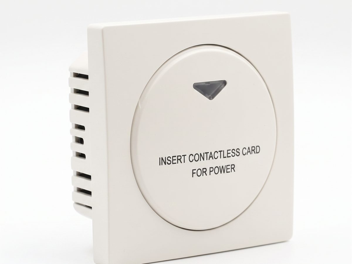
مفتاح بطاقة الفندق — التحكم في طاقة غرفة الضيوف
مفتاح بطاقة الفندق للتحكم في طاقة غرفة الضيوف. كشف بطاقة RFID/IC، إدخال البطاقة لتشغيل الطاقة، فصل الطاقة بتأخير زمني عند إزالة البطاقة. تيار متردد 220 فولت، 10A-16A، RS485 أو تلامس جاف. CE RoHS. مورد OEM/ODM.
تشير هذه الصفحة بالفعل إليه كمرجع تالٍ موصى به.
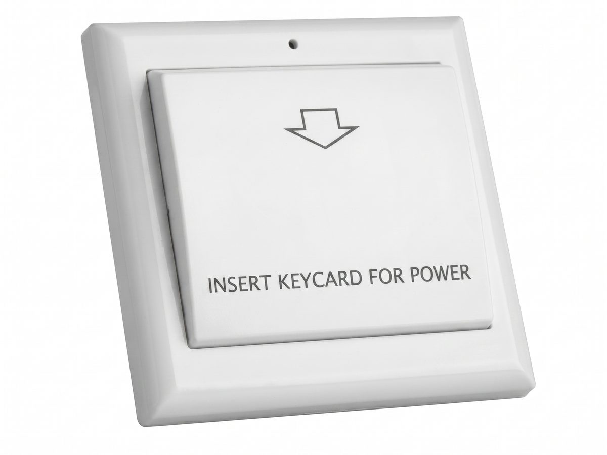
ملحقات مفتاح بطاقة المفتاح — لوحات الوجه، صناديق 86، الملامسات والطاقة
ملحقات مفتاح بطاقة المفتاح لتركيب صندوق 86: لوحات الوجه، قواعد تركيب صندوق 86، ملامسات لأحمال تكييف الهواء العالية، مصادر طاقة، ومحاور RS485. اختر الملحقات لإكمال أي مشروع مفتاح بطاقة مفتاح صندوق 86.
تشير هذه الصفحة بالفعل إليه كمرجع تالٍ موصى به.
حلول ذات صلة
3التحكم في طاقة غرفة الفندق باستخدام مفاتيح البطاقات
حل عملي للتحكم في طاقة غرفة الفندق لتشغيل إضاءة وتكييف ومنافذ غرفة الضيوف من بطاقة غرفة مصرح بها.
تشير هذه الصفحة بالفعل إليه كمرجع تالٍ موصى به.
نظام إدارة الغرف الفندقية القائم على التحكم بالطاقة عبر البطاقة
نظام عملي لإدارة الغرف الفندقية للتحكم في طاقة الغرفة عبر مفاتيح البطاقة، والموصلات، وقواعد التشغيل الموثقة بوضوح.
إنه يدعم نفس سياق المنتج: مفتاح بطاقة الفندق — التحكم في طاقة غرفة الضيوف.
توفير طاقة الفندق باستخدام مفتاح تشغيل غرفة الضيوف
حل لتوفير طاقة الفندق يستخدم تشغيل الغرفة المتحكم به بالبطاقة لمنع الأضواء وتكييف الهواء والمآخذ المختارة من العمل دون داعٍ.
إنه يدعم نفس سياق المنتج: مفتاح بطاقة الفندق — التحكم في طاقة غرفة الضيوف.
مقالات المدونة ذات الصلة
3
مفتاح بطاقة الفندق: الأنواع، الموديلات، وكيفية المواصفات
يغطي مفتاح بطاقة الفندق موديلات العام، RFID، TTLOCK، BLE، والإشغال. يرشدك هذا الدليل لعائلة مفتاح البطاقة المصطلحات الرئيسية والمواصفات.
إنه يدعم نفس سياق المنتج: مفتاح بطاقة الفندق — التحكم في طاقة غرفة الضيوف.
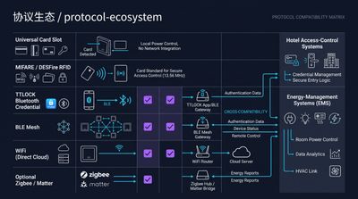
RFID vs NFC لمفاتيح بطاقات الفنادق: أي تقنية بطاقة تختار؟
يعتمد الاختيار بين RFID و NFC لمفاتيح بطاقات الفنادق على المدى والقفل: RFID بتردد 125 كيلوهرتز / 13.56 ميجاهرتز (MIFARE، Temic) هو المعيار الفندقي لتغذية الغرف
إنه يدعم نفس سياق المنتج: مفتاح بطاقة الفندق — التحكم في طاقة غرفة الضيوف.
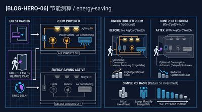
ما هو مفتاح بطاقة الفندق وكيف يوفر طاقة الغرفة
مفتاح بطاقة الفندق هو جهاز حائطي يشغل غرفة الضيف عند إدخال البطاقة ويفصل التيار عند سحبها، مما يوفر عادةً 25-40% من كهرباء الغرفة.
إنه يدعم نفس سياق المنتج: مفتاح بطاقة الفندق — التحكم في طاقة غرفة الضيوف.
حدد مشروع فندقك مع مهندسينا
أخبرنا بعدد الغرف ونوع السقف والبروتوكول المفضل. سنعود إليك بخطة عينات وعرض سعر خلال 24 ساعة عمل.
- انتقل من الإرشادات العامة إلى نقاش حول المنتج أو التطبيق.
- استخدم RFQ عندما يحتاج التسعير أو الرسومات أو MOQ أو توقيت الإطلاق إلى هيكلة.
- أبقِ مسار اتصال مباشر ظاهرًا للتوضيحات السريعة والتسليم.